

Building Innovation: Mix and Match Your BI2024 Tracks
A Project BIM Execution Plan (BEP) is a foundational planning document to define the implementation strategy for BIM on a project. BIM Execution Planning is crucial for successfully implementing BIM on a project. This standard defines an approach to developing and expanding a BEP at several stages: the owner outlines BIM needs in the request for proposal, proposing parties submit a Proposal BEP, and then the chosen team collaborates on developing a Project BEP. This progression of developing a detailed BEP ensures that all parties explore BIM opportunities to meet project goals, maximize the value of the BIM process and deliverables, and minimize waste during the project.
By developing a BEP, the project and project team members can achieve the following value:
Ultimately, the entire team will gain value through the increased level of planning by reducing the unknowns in the implementation process, thereby reducing the overall risk to all parties and the project.
The primary audience of the BEP module is the owner and the project delivery team members for all projects that plan to implement BIM at any stage of the delivery process. The standard and resources are developed to support various project types, from buildings to infrastructure.
The BEP Standard and resources can be implemented during the owner's pre-planning phase and updated as new activities are planned throughout the project lifecycle. The BEP can be developed across three phases within the delivery process. These include:
This module includes the following items:
The owner can leverage this module to clearly document their BEP requirements on a project. Please reference the Project BIM Requirements module for additional information regarding BEP requirements. The owner can also leverage the template to develop an RFP BEP if they wish to distribute an initial BEP with the RFP. A proposal team can use the BEP template to respond to the RFP, and all project team members can leverage the standards and guidelines to develop the Project BEP.
This module is an updated section within the NBIMS-US™ BEP Workgroup. The workgroup includes professionals from the global industry who reviewed and incorporated national and international BIM standards, including ISO 19650 principles. The first version of the BEP Standard was approved for NBIMS-US™ Version 2.0. This version has significant revisions and replaces the previous version. The primary changes include a significantly revised definition of required and optional content elements for a Project BEP at various stages in the delivery process. It also includes new resources to support adoption through a spreadsheet template and JSON information exchange format.
A Project BIM Execution Plan (BEP) is a foundational planning document to define the implementation strategy for BIM on a project. This is the second version of a BIM Execution Planning Standard in the U.S. National BIM Standard. The first version was approved for NBIMS-US™ Version 2.0. This version has significant revisions and replaces the first version. The main changes include a clear definition of both required and optional content elements for a BEP at various stages in the delivery process. It includes a phased approach to BEP development, including owner requirements and infrastructure templates.
This document was prepared by the BIM Execution Planning (BEP) Workgroup of the National BIM Standard Project. In addition to this standard, NBIMS-US™ includes a BEP Standard User’s Guide, a Guide to Developing a BEP, a BEP Template, and an information exchange definition for digitally transacting a BEP from one software product to another.
This BIM Execution Plan (BEP) Standard defines a sequence of activities and information requirements to be supplied by the various participants when developing a project-level Building Information Management (BIM) Execution Plan (hereinafter referred to as the BEP). This Standard is for all participants supporting BIM use on a project.
The BEP activities are designed to develop a proposer BEP, the proposal BEP, and finally, the project BEP once the project is awarded. The information for each of these activities is identified as required or optional in this standard.
The Standard concludes with an appendix of the information requirement tables (Excel BEP Requirements), including sample data and field names for each element. The template may be used to develop specific BEP requirements by an owner or to structure a database or information exchange for a BEP.
This standard defines the elements of project BIM requirements that the owner (also known as the Appointing Party in ISO 19650-2 (2018)) would include in the Owner Project Requirements (OPR). It is intended for an owner to use to define Project BIM Requirements for delivery team members (also known as the Appointed Party in ISO 19650-2 (2018)). This standard is intended to define the minimum requirements for a viable BIM project. An owner may extend requirements beyond the scope of this standard to include other BIM uses or BIM implementation.
The following documents are referenced throughout this Standard:
The entity that is contracted for and provides information concerning works, goods, or services.
[Source: ISO 19650-1:2018(en), modified – added ‘the entity that is contracted for and provides’]
[Also known as contractor, designer, consultant, architect, engineer, subcontractor, subconsultant]
The entity that holds the contract and receives information concerning works, goods, or services.
[Source: ISO 19650-1:2018(en), modified – added ‘the entity that is contracted for and receives’]
[Also known as owner, client]
An agreed instruction for the provision of information concerning works, goods or services.
[Source: ISO 19650-1:2018(en), modified – added the word ‘An’ at the beginning]
Note 1: This term is used whether or not there is a formal contract or agreement between the parties.
A plan that explains how the information management aspects of an appointment will be carried out by the delivery team.
[Source: ISO 19650-2:2018(en), 3.1.3.1, modified – revised to add ‘A’ as the first word and revise ‘the appointment’ to ‘an appointment’]
A plan that explains how the information management aspects of a project will be carried out by the project team.
[Source: ISO 19650-2:2018(en), 3.1.3.1 – modified ‘delivery team’ to ‘project team’]
See Appointment BIM Execution Plan (ABEP) and Project BIM Execution Plan (PBEP).
A process that a team or party uses to develop a BEP.
A graphical representation of a Building Information Management (BIM) process for a project.
[Source: BEP Module, NBIMS-US™, V4]
The purpose for applying BIM. BIM Use includes name, definition, and related terms.
[Source: BIM Use Definitions Module, NBIMS- US, V4]
A specific methodology and outcome achieved when applying a BIM Use on a project(s) or within an organization(s). A BIM Uses Case includes a BIM Use name, followed by the method, followed by the outcome.
[Source: BIM Use Definitions Module, NBIMS-US, V4]
A graphical representation of a Building Information Management (BIM) process for a specific BIM Use.
Functions of controlling the acquisition, analysis, retention, retrieval, and distribution of built environment asset information all within an information processing system.
[Source: ISO/IEC 20944-1:2013(en), modified term – added “building” to specify information about built environment assets, and modified the definition – added ‘built environment asset’ to the definition of Information Management to clarify the specific management of ‘building’ information.]
Note: Within the term, ‘building’ refers to the process of building a built environment asset, not a specific type of facility. BIM is a function that can be implemented across all types of built environment assets, including buildings, bridges, highways, tunnels, process plants, landscape, and other infrastructure and facility types.
A shared digital representation of physical and functional characteristics of a built environment asset.
[Source: NBIMS-US™ Version 3, modified – added the word ‘shared’ and added the words ‘and built asset’– see Note 2 and Note 3]
Note 1: NBIMS-US™ Version 3 also included “As such it serves as a shared knowledge resource for information about a facility, forming a reliable basis for decisions during its life cycle from inception onwards.”
Note 2: Added the word ‘shared’ to the definition to be more consistent with ISO/TS 12911:2012(en) definition. The ISO definition uses the term ‘built object’ instead of ‘facility’ and adds facility types including ‘buildings, bridges, roads, process plant’.
Note 3: Added the words ‘built environment assets’ to specify that a building information model can include representations of buildings, roads, bridges, plants, and other built assets.
Generating and using a shared digital representation of a built environment asset to facilitate design, construction, and operation processes to form a reliable basis for decisions.
[Source: ISO 19650-1:2018(en), 3.3.14, modified – revised ‘Use’ to ‘Generating and using’]
An agreed source of information for any given project or asset, for collecting, managing and disseminating each information container through a managed process.
[Source: ISO 19650-2:2018(en), modified - added ‘An’ as the first word]
Note: A CDE workflow describes the processes to be used and a CDE solution can provide the technology to support those processes.
The collection of entities who are contracted or appointed for works, goods, or services.
[Source: NBIMS-US™ V3, modified – added “or appointed” and the note]
Note: Delivery team includes all appointed parties for the planning, design, and construction of a project.
The entity that is contracted for and provides information concerning works, goods, or services.
A physical structure(s) or installation(s), including related site works, serving one or more main purposes.
[Source: ISO/TS 12911:2012(en), 3.9, modified - added ‘A’ as the first word and ‘(s)’ to structure and installation]
Note: Examples of physical structure(s) or installation(s) can include buildings, bridges, highways, tunnels, process plants, and other infrastructure and facility types.
A system of models consisting of linked but distinct components derived from multiple data sources that do not lose their identity or integrity.
Act of satisfying an information requirement or part thereof through storing, accessing, transferring, and archiving information.
[Source: ISO 19650-1:2018(en), 3.3.7 – added ‘through storing, accessing, transferring, and archiving information’]
Concepts and principles used across the built environment sector to support the management and production of information during the life cycle of built assets.
[Source: ISO 19650-1:2018(en)]
A specification for what, when, how and for whom information is to be produced.
[Source: ISO 19650-2:2018(en), modified - added ‘A’ as the first word]
A specification defining the reliable geometric information used to represent model elements.
Data that defines and describes other data.
[Source: ISO 1087-1:2000, 3.2.18]
A portion of the model(s) representing a component, assembly, or construction entity (part) which, in itself or in combination with other parts, fulfills a predominating function of a construction entity.
The party responsible for creating or updating any given model element.
The entity that holds the contract and receives information concerning works, goods, or services.
[Source: ISO 19650-1:2018(en) defined as appointing party, added ‘the entity that is contracted for and receives’]
[Also known as appointing party*]
*Note: NBIMS-US™ recognizes the term appointing party, but uses the term owner in the standard documents as it is recognized as the common term used in the US market. These should be considered interchangeable.
A written document that details the ideas, concepts, and criteria required by the appointing party, and the requirements upon which works, goods, and services are based.
Note: Appointing Party's Project Requirements (APPR) is an alternative term.
A sequence or flow of activities in an organization with the objective of carrying out work.
[Source: Business Process Model and Notation (BPMN) Version 2.0.2, Object Management Group, December 2013]
A collaborative plan that explains how the information management aspects of the project delivery process will be carried out by the delivery team.
Note: Adapted from ISO 19650 definition for BIM Execution Plan to describe the collaborative plan at a project level, instead of an appointment level plan.
Desired and measurable outcomes to achieve project success that add value to the project.
A discrete point in time associated with a project outcome.
Owner [Appointing Party] and all delivery teams.
[Source: ISO 19650-1:2018(en), added “owner”]
A set of processes that involve Quality Planning, Quality Assurance, and Quality Control as applied to the management of information.
[Source: ISO 13584-101:2003, 3.28]
A project BIM execution plan (BEP) is developed by a project team through a collaborative process at various stages within the project deliverable (see Figure 1). As defined by ISO 19650-2 (2008), an owner (also known as the Appointing Party within the ISO standard) should define their BIM requirements and standards prior to the solicitation of delivery team members (known as lead Appointed Parties or Appointed Parties within ISO 19650-2).
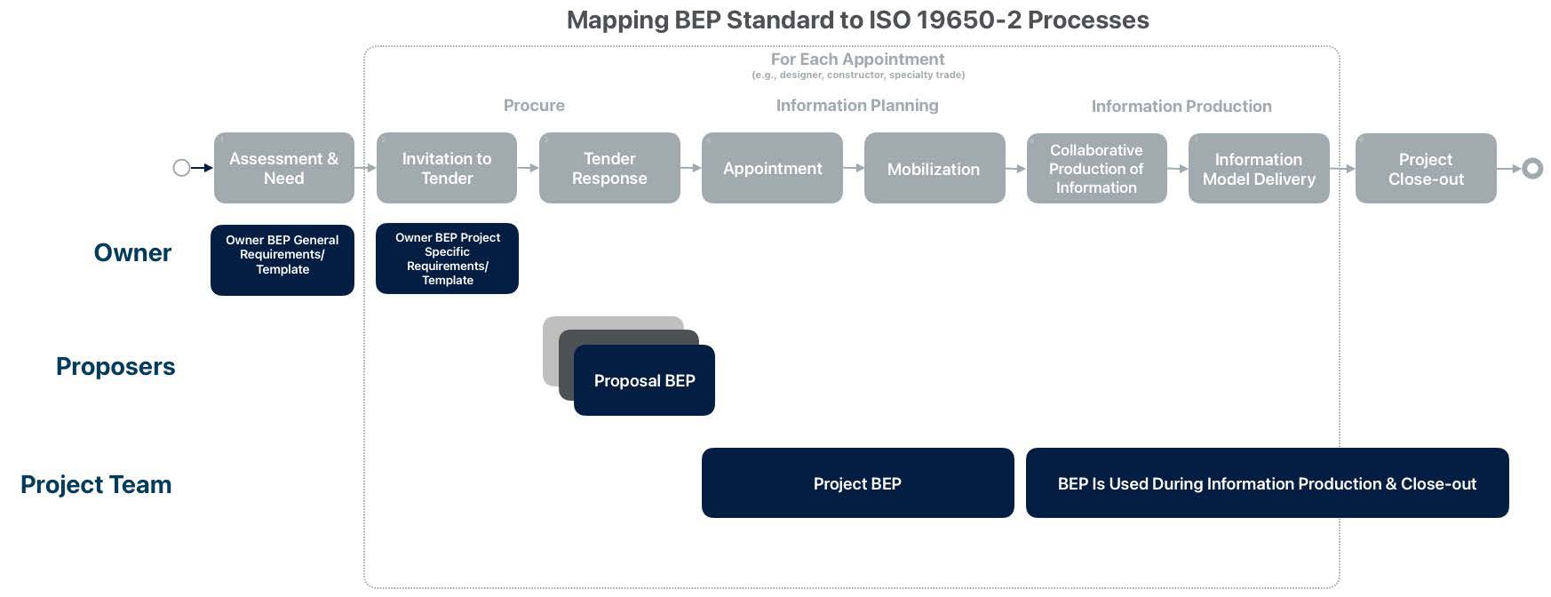
Figure 1: Mapping BIM Execution Planning submissions to ISO 19650-2 processes
This Standard focuses on defining project-level BEPs at three stages within the delivery process. A core set of BEP information is needed from the owner for proposal organizations and selected team members to achieve the owner’s goals and align with the owner’s information management practices. The three stages in the Standard include:
Additional considerations regarding the project BEP:
A project-level BEP may include the following information categories and elements. See Chapter 6 for more specific field types and whether the categories and elements are required or optional at the three BEP stages defined in Chapter 4.
Defines the BEP Metadata including the origin, location, version, approval status, and acknowledgments for the developed project BEP.
Defines the critical information related to the project for reference in the development of the BEP.
Defines the contact information for key project organizations and personnel.
Defines the roles in each organization and their responsibilities related to the information management processes on the project, including which organizations will perform each selected BIM Use.
Documents the core attributes of each considered BIM Use in a table along with evaluation criteria used to select the BIM Use. Reference the BIM Use Definition section of NBIMS-US™ for additional details regarding BIM Uses and BIM Use Cases.
Documents the overall process for BIM execution, along with detailed maps for the selected BIM Use Cases.
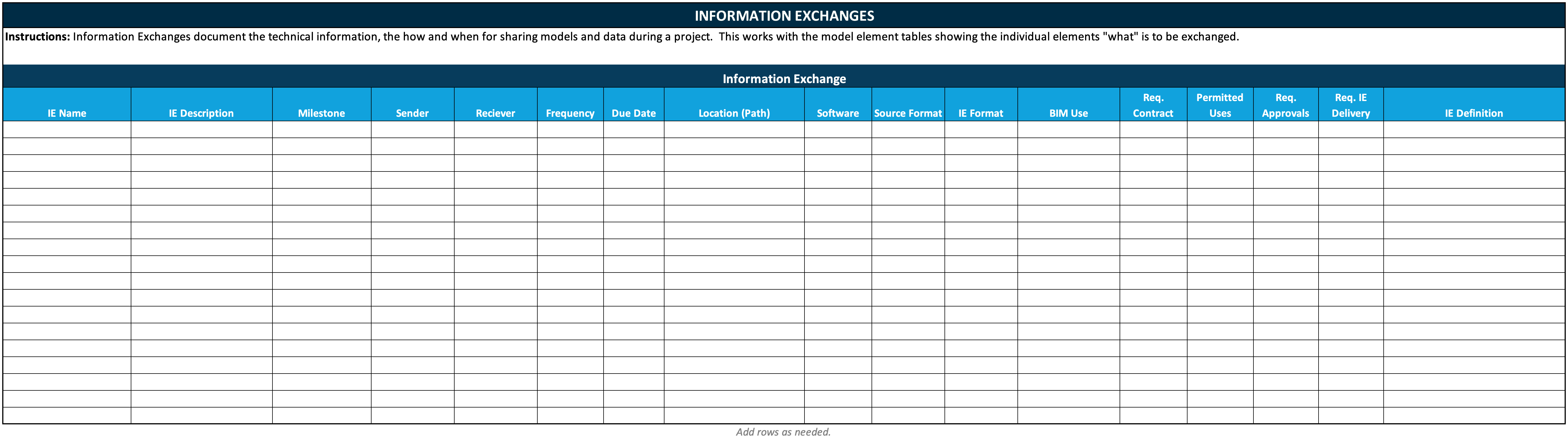
Documents the information exchanges created as part of the planning process in the BEP.
Documents the electronic and collaboration activity procedures used by the project team members. This includes the definition of model management procedures as well as typical meeting schedules and agendas.
Defines the project team’s overall quality management plan, including a quality assurance program for model creation and a quality control plan for defining and validating model quality.
Documents the specification and requirements for software, hardware, and other information technology requirements.
Defines how the model is to be created, named, divided (if needed), federated, and organized, as well as the standards that will be used during the project.
Documents the register of information management risk items for the project.
The following tables for each BEP category include the information item and description from Section 5. The tables also include example values, a field name for each information item, a field type for the information, and the time that the information may or shall be added to the BEP.
| Information Item | Description | Examples | Field Name | Field Type | RFP BEP (by Owner) | Proposal BEP (by Proposer) | Project BEP (by Team) |
|---|---|---|---|---|---|---|---|
| BEP Path | A path to the BEP location. This location could be an online data source or a file location and file name. | http://bim.psu.edu/sampleBEP.pdf | BEPPath | URL | R | R | R |
| BEP Data Format | A description of the format used for storing the BEP data elements. | .PDF, .XLS, .DB, .JSON | BEPDataFormat | Text | R | R | R |
| BEP Executive Summary | A summary description of the BEP document developed to briefly communicate the contents and status of the BEP. | This BIM Execution Plan documents the team's approach to managing the information regarding the facility throughout the planning, design and construction process, and including information delivery to support operations. | BEPExecutiveSummary | Text | R | R | R |
| Cover Page Image | A path to an image of the BEP cover. | http://bim.psu.edu/samplecoverimage.png | BEPCoverPage | URL | O | O | O |
| BEP Version Log | A table that includes all BEP versions. | (a table) | BEPVersion | Array | R | R | R |
| BEP Version Number | A version number for each BEP version. | Version 1.1 | BEPVersion.Number | Text | R | R | R |
| BEP Version Date | The date for the BEP version. | 20-Jun-22 | BEPVersion.Date | Date | R | R | R |
| BEP Version Description | A description of the specific BEP Version. | Original BEP developed by the Architect from the RFP BEP. | BEPVersion.Description | Text | R | R | R |
| BEP Version Creator Organization | The lead author organization who released the version of the BEP. | XYZ Architects | BEPVersion.CreatorOrganization | Text | R | R | R |
| BEP Version Creator Contact | The lead author contact who released the version of the BEP. | Jane Doe | BEPVersion.CreatorContact | Text | R | R | R |
| Approval Organization | The organization that may or should approve the BEP, depending upon contractual requirements. | ABC Owner | BEPVersion.ApprovalOrganization | Text | O | O | O |
| Approval Contact | The contact that may or should approve the BEP, depending upon contractual requirements. | Jim Doe | BEPVersion.ApprovalContact | Text | O | O | O |
| Approval Status | The status of the approval from the approval organization/contact. | Draft or Approved or Shared | BEPVersion.ApprovalStatus | Text | O | O | O |
| OPR Waivers | A table of all requested and approved waivers to the Owner Project Requirements. | Table | OPRWaiver | Array | O | O | O |
| Waiver Name | A name that represents the content of the Owner Project Requirement waiver. | Architectural Modeling Software Modification | OPRWaiver.Name | Text | O | O | O |
| Waiver Description | A description of the Owner Project Requirement waiver. | Request the use of Software A instead of Software B for the development of the Architectural Model and corresponding native file delivery modification. | OPRWaiver.Description | Text | O | O | O |
| Waiver Requested By | The organization requesting the Owner Project Requirement waiver. | Contractor A | OPRWaiver.RequestedBy | Text | O | O | O |
| Waiver Status | The waiver review or approval status. | Approved by Owner; Requested and In Review; Rejected | OPRWaiver.Status | Text | O | O | O |
| BEP Standard Used for Development | The BIM Execution Planning standard that is used to defined the required information categories, elements, and attributes contained within the BEP. | NBIMS-US™, BEP Standard Version 4.0 | BEPStandardUsed | Text | O | O | O |
| Acknowledgements | Acknowledgement of any creative commons or other copyrighted sources used for developing the BEP and any specific individual or organizational acknowledgements. | NIBS for BEP Standard Creative Commons license. | BEPAcknowledgements | Text | O | O | O |
Time of Entry | R=Required & O=Optional)
| Information Item | Description | Examples | Field Name | Field Type | RFP BEP (by Owner) | Proposal BEP (by Proposal) | Project BEP (by Team) |
|---|---|---|---|---|---|---|---|
| Project Name | A unique name for the project scope. | Bridge Project ABC | ProjectName | Text | R | R | R |
| Project Owner Name | The formal organizational name for the owner of the project. | Department of Transportation ABC | ProjectOwnerName | Text | R | R | R |
| Project Legal Address | The legal address for the project location. | Street, City, State Zip | ProjectAddress | Address | R | R | R |
| Project Description | A brief description of the project. | The project includes the construction of a new 100' long bridge over the xyz stream along with all associated paving, guard rail, associated with the project. | ProjectDescription | Text | R | R | R |
| Project Delivery Method | A description of the project delivery method used for contracting with the prime contracted entities with the owner. | Design-Bid-Build with low-cost selection of the prime construction contractor | ProjectDeliveryMethod | Text | O | O | O |
| Team Selection Procedure | Description of the approach to select the team members to complete the project. | Low Cost; Best Value Selection | TeamSelection | Text | O | O | O |
| BIM Contracting Procedure | A description of any specific BIM-related contracting procedures to be used on the project. | The designer will have clear BIM requirement, etc. | BIMContracting | Text | O | O | O |
| Owner Modeling Guide Title | The title of the owner modeling guide(s) to meet the owner project requirements. | State XYZ Design Modeling Guide, Version 1.0 | OwnerModelingGuide | Text | O | O | O |
| Owner Modeling Guide Location | The path to the owner modeling guide(s). | http://dot.gov/modelingguide | OwnerModelingGuideLocation | URL | R | R | R |
| Project Information Requirements Title | A title for the Project Information Requirements for the project. | Project X Information Deliverable Requirements | ProjectInformationRequirementsTitle | Text | R | R | R |
| Project Information Requirements Location | The path to the Project Information Requirements. | http://dot.gov/projectinformationrequirements | ProjectInformationRequirementsLocation | URL | R | R | R |
| Facility Type Classification | The classification value for the type of facility. This number could be the OmniClass Table 11 number or a unique value system from the owner. | 11-12 21 31 | FacilityTypeClassification | Text | O | O | O |
| Facility Type Name | The name of the type of facility. The owner may have a proprietary list of facility types or the team should include the facility type from OmniClass Table 11. | High School | FacilityTypeName | Text | O | O | O |
| Project Identification Table | A table with the identification numbers used by project team members to identify the project. | (a table) | ProjectID | Array | O | O | O |
| Project Identification Description | A description of the type of project identification used. | Bridge Identification Number; Owner Project Reference Number | ProjectID.Description | Text | O | O | O |
| Project Identification Value | The value of the project identification item. | District 2, Bridge 234; Project 12345 | ProjectID.Value | Text | O | O | O |
| Project Certifications Table | A table that identifies the relevant project certifications along with the value of each certification. Examples of certifications can include environmental sustainability certification (e.g., LEED or Green Globes), structural facility certifications (e.g., OSHPD compliance), or other relevant certifications. | (a table) | Certification | Array | O | O | O |
| Certification Information | Title of the type of certification. | LEED | Certification.CertificationName | Text | O | O | O |
| Certification Value | The goal (if the project is in progress) or value achieved (if the project is complete). | Gold | Certification.CertificationValue | Text | O | O | O |
| Project Metrics Table | A table that defines core metrics for categorizing or classifying the project scope, scale or characteristics. | (a table) | MetricsTable | Array | O | O | O |
| Project Metric Name | The name of the project metric type used on a project. | Bridge Length | MetricsTable.MetricName | Text | O | O | O |
| Project Metric Value | Quantitative value of the metric on the project. | 100 | MetricsTable.MetricValue | Number | O | O | O |
| Project Metric Unit | Unit of measure for the metric. | Feet | MetricsTable.MetricUnit | Text | O | O | O |
Time of Entry (R=Required & O=Optional)
| Information Item | Description | Examples | Field Name | Field Type | RFP BEP (by Owner) | Proposal BEP (by Proposer) | Project BEP (by Team) |
|---|---|---|---|---|---|---|---|
| Organization | A table with all core organizations related to BIM scopes of work on the project. | (a table) | Organization | Text | R | R | R |
| Organization Name | The formal name of the organization. | ABC Owner | Organization.OrganizationName | Text | R | R | R |
| Abbreviation | Abbreviation of the organizational name for use in BEP tables. | ABC; Construction | Organization.Abbreviation | Text | O | O | O |
| Phone Number | The main phone number for the organization. | +1 (202) 555-0144 | Organization.PhoneNumber | Phone Number with Country Code | O | R | R |
| Office Location | The primary office location for the organization. | 02 Street, Washington, DC 20001 | Organization.OfficeLocation | City, State, Country | O | R | R |
| Organization Role | The primary role of the organization on the project. | Owner, Prime Designer, Prime Constructor | Organization.OrganizationRole | Text | O | R | R |
| Contact | A table for all core contacts related to BIM scopes of work on the project. | (a table) | Contact | Array | R | R | R |
| Organization Name | The formal name of the primary organization for a contact. | ABC Owner | Contact.Organization | Text | R | R | R |
| Contact Name | The name of the contact. | Jim Doe | Contact.ContactName | Text | R | R | R |
| Contact Role | The primary role of the contact on the project. | Information Manager | Contact.ContactRole | Text | R | R | R |
| Email Address | The primary email address of the contact. | jmcbim@abcowner.gov | Contact.EmailAddress | R | R | R | |
| Phone Number | The primary phone number for the contact. | +1 (202) 555-0198 | Contact.PhoneNumber | Phone Number | R | R | R |
| Primary Location | The primary location for the contact. | 01 Street, Washington, DC 20001 | Contact.PrimaryLocation | Address, City, State, Country | O | O | O |
Time of Entry (R=Required & O=Optional)
| Information Item | Description | Examples | Field Name | Field Type | RFP BEP (by Owner) | Proposal BEP (by Proposer) | Project BEP (by Team) |
|---|---|---|---|---|---|---|---|
| BIM Roles | A table to define the roles and responsibilities related to the information management process on the project. | (a table) | Role | Array | O | R | R |
| Role Name | The name of a role, e.g., BIM Manager, Project Manager, etc. | Information Manager, BIM Manager | Role.Name | Text | O | R | R |
| Role Description | A general description of the role. | (reference the Core BIM Requirements for common role definitions) | Role.Description | Text | O | R | R |
| Role Responsibility | The responsibilities of individuals within this role as it relates to the information management processes of the project. | (reference the Core BIM Requirements for common role responsibility) | Role.Responsibility | Text | O | R | R |
| Required by Contract | A value to define whether the role is required by contract. | Yes, No | Role.ContractRequired | Text | O | O | O |
| Role Code | A unique role categorical value if an entity uses a code value. | IM, PM | Role.Code | Text | O | O | O |
Time of Entry (R=Required & O=Optional)
| Information Item | Description | Examples | Field Name | Field Type | RFP BEP (by Owner) | Proposal BEP (by Proposer) | Project BEP (by Team) |
|---|---|---|---|---|---|---|---|
| Project Phases | A table of project phases. A phase is a duration of time associated with a project task(s). | (a table) | Phase | Array | R | R | R |
| Phase Name | The name of the project phase. | Conceptual Design | Phase.Name | Text | R | R | R |
| Phase Description | The description of the project phase. | The initial design phase to identify the general form and function of the facility to an approximate level of 30% design completion. | Phase.Description | Text | O | O | O |
| Estimated Start date | The estimated start date for the phase. | 1/1/2022 | Phase.EstimatedStartDate | Date | R | R | R |
| Estimated Completion Date | The estimated completion date for the phase. | 6/30/2022 | Phase.EstimatedCompletionDate | Date | R | R | R |
| Actual Start Date | The actual start date for the project phase (if started). | 2/1/2022 | Phase.ActualStartDate | Date | O | O | O |
| Actual Completion Date | The actual completion date for the project phase (if complete). | 7/1/2022 | Phase.ActualCompletionDate | Date | O | O | O |
| Project Milestones | A table of project milestones. A milestone is a discreet point in time associated with a project outcome. | (a table) | Milestone | Array | R | R | R |
| Milestone Name | The name of the project milestone. | Conceptual Design Complete | Milestone.Name | Text | R | R | R |
| Milestone Description | The description of the project milestone. | Date of completion for the building program. | Milestone.Description | Text | O | O | O |
| Estimated Date | Estimated schedule date for the milestone (prior to milestone completion). | 12/1/2022 | Milestone.EstimatedDate | Date | R | R | R |
| Actual Date | Actual milestone completion date (if complete). | 11/1/2022 | Milestone.ActualDate | Date | O | O | O |
| Phase (key reference to Phase) | The project phase in which the milestone exists (reference Phase table). | Conceptual Design | Milestone.Phase | Text (reference Phase) | R | R | R |
Time of Entry (R=Required & O=Optional)
| Information Item | Description | Examples | Field Name | Field Type | RFP BEP (by Owner) | Proposal BEP (by Proposer) | Project BEP (by Team) |
|---|---|---|---|---|---|---|---|
| Project Goals | A table of project goals that identifies actions and outcomes that add value to the project. | (a table) | Goal | Array | R | R | R |
| Goal Description | A project goal defines a desired outcome needed for project success. Some project goals are most effectively achieved using BIM. The goals, aligned BIM Uses, and the desired outcomes and deliverables are documented in the BEP. | Increase design quality by clearly documenting the initial program requirements and performing design reviews with stakeholders. | Goal.Description | Text | R | R | R |
| Priority | The priority of the defined goal. Goals and BIM Uses are prioritized based upon need for project success and any constraints to achieving the desired outcome. | Essential, High, Medium, Low | Goal.Priority | Text | O | O | O |
| Potential BIM Uses to Support Goal | A BIM Use that has the potential to enhance the goal. See the NBIMS-US™ BIM Use Definition section for BIM Uses. | Author Design, Review Design Models, Coordinate Design Models | Goal.PotentialBIMUses | Text | O | O | O |
| Goal Customer | The customer for the goal who requires the deliverable to move the project forward. | Owner | Goal.Customer | Text (reference Organization) | R | R | R |
| Goal Primary Responsible Party | The primary party that will be responsible for achieving the goal through BIM. | Architect | Goal.ResponsibleParty | Text (reference Organization) | R | R | R |
| Constraints | The constraint(s) that limits the ability to achieve a goal. | Software availability; model federation; level of development | Goal.Constraints | Text | O | O | O |
| Goal Phase | The phase(s) of the goal. At what point in the project does execution of the BIM Use provide the most value to the project. | Design phase | Goal.Phase | Text (reference Phase) | O | O | O |
Time of Entry (R=Required & O=Optional)
| Information Item | Description | Examples | Field Name | Field Type | RFP BEP (by Owner) | Proposal BEP (by Proposer) | Project BEP (by Team) |
|---|---|---|---|---|---|---|---|
| BIM Use Table | A table to define attributes of each BIM Use along with evaluation criteria used to select the BIM Use. | (a table) | BIMUse | Array | R | R | R |
| BIM Use Name | The name of the BIM Use | Author Design | BIMUse.Name | Text | R | R | R |
| BIM Use Method | The method used to achieve the BIM Use purpose. | Using 3D parametric modeling software | BIMUse.Method | Text | O | R | R |
| BIM Use Outcome | The outcome desired from the implementation of the BIM Use. | Develop design intent model. | BIMUse.Outcome | Text | R | R | R |
| BIM Use Definition | The definition of the BIM Use. | Develop design using BIM for the architectural, mechanical, structural and electrical systems. | BIMUse.Definition | Text | R | R | R |
| BIM Use Value to Project | The value of the BIM Use to the project. | High | BIMUse.Value | Text | O | O | O |
| BIM Use Responsible Party | The primary responsible party for implementing the BIM Use. | Architect | BIMUse.RP | Text | O | O | O |
| Value to Responsible Party | The value of the BIM Use to the primary party. | High | BIMUse.ValueToRespParty | Text | O | O | O |
| Resource Availability for BIM Use | The resource availability for implementing the BIM Use. | Designers and tools are available. | BIMUse.ResourceAvailability | Text | O | O | O |
| Competency Level with BIM Use | The competency level of the responsible party for implementing the BIM Use. | Designers are competent with BIM software. | BIMUse.CompetencyLevel | Text | O | O | O |
| Experience Level with BIM Use | The historical experience of the key team members of the responsible party for implementing the BIM Use. | Designers are experienced with developing models. | BIMUse.ExperienceLevel | Text | O | O | O |
| Additional Resources/Competencies Required to Implement | Additional resources needed to implement the BIM Use. | None | BIMUse.NeededResources | Text | O | O | O |
| Additional Training Required for BIM Use Implementation | Additional training needed to implement the BIM Use. | None | BIMUse.NeededTraining | Text | O | O | O |
| Proceed Decision | The decision regarding whether to proceed with the BIM use. | Yes, Maybe, No | BIMUse.Implementation | Text | R | R | R |
| Software Required for Use | The requirement for a specific software application to be used for the BIM Use, if any. | Software XYZ is Required | BIMUse.Software | Text | O | O | O |
| BIM Use Project Phase | The phase(s) in which the BIM Use will be implemented. | Design Phases | BIMUse.Phase | Text | O | O | O |
| Notes | Notes regarding the BIM Use. | The architectural model will provide the reference for the mechanical, structural and electrical systems models. | BIMUse.Notes | Text | O | O | O |
Time of Entry (R=Required & O=Optional)
| Information Item | Description | Examples | Field Name | Field Type | RFP BEP (by Owner) | Proposal BEP (by Proposer) | Project BEP (by Team) |
|---|---|---|---|---|---|---|---|
| BIM Process Diagram - Level 1 | The path to a detailed process diagram for the execution of each BIM Use, which also identifies the information exchanges and process workflow. | http://BIMMaps/Level1Diagram.pdf | BIMProcess | URL | O | R | R |
| BIM Use Process Diagrams - Level 2 | A table of the BIM uses with their associated BIM Use process diagram. | (a table) | BIMUseProcess | Array | O | O | R |
| BIM Use Name (link to BIM Use) | BIM Use name for the Level Two process diagram. | Author Design | BIMUseProcess.Name | Text | O | O | R |
| BIM Use Process Diagram Path | A path to the process diagram of the activities, information exchanges, and process workflow for the BIM Use. | http://BIMDiagrams/Level1Diagram.pdf | BIMUseProcess.ProcessDiagramPath | URL | O | O | R |
Time of Entry (R=Required & O=Optional)
| Information Item | Description | Examples | Field Name | Field Type | RFP BEP (by Owner) | Proposal BEP (by Proposer) | Project BEP (by Team) |
|---|---|---|---|---|---|---|---|
| Information Exchange Table | A table that defines the characteristics of each information exchange on the project. | (a table) | IE | Text | R | R | R |
| Information Exchange Name | The name of the information exchange. | Design Model | IE.Name | Text | R | R | R |
| Information Exchange Description | A description of the purpose and general contents of the information exchange. | The design intent model at the completion of the design phase including architectural, structural, and MEP design content. | IE.Description | Text | R | R | R |
| Milestone | The milestone that is associated with the information exchange. | Design phase | IE.Milestone | Text | R | R | R |
| Information Sender | The responsible party for creating the information. | Designer | IE.Author | Text | O | O | R |
| Information Receiver(s) | The organization(s) to receive the file. | Constructor | IE.Receiver | Text | O | O | R |
| Frequency | The frequency of the information exchange. | One Time, Every Month | IE.Frequency | Text | O | O | R |
| Due Date | The date that the initial (if iterative) or final (if one time) submission is due. | 11/11/2022 | IE.DueDate | Date | O | O | R |
| Information Location | The path to the location of the information exchange. | https://sample_data_location | IE.ModelFile | URL | O | O | R |
| Information Modeling Authoring Software | The software used to develop the information. | Revit, ArchiCAD, OpenRoads | IE.ModelSoftware | Text | O | O | R |
| Native Information Source Format | Native data source type, e.g., a specific file format. | .rvt, .dgn, .xls | IE.NativeFileFormat | Text | O | O | R |
| Information Exchange Format(s) | Information exchange format, e.g., IFC, other open formats, other proprietary formats. | .ifc, .xls, .pdf, .idsxml | IE.ExchangeFileFormat | Text | O | O | R |
| BIM Use | The BIM Use that develops the information exchange. | Author Design | IE.BIMUse | Text | R | R | R |
| Required by Contract | A value to define whether an information exchange is required by contract. | Yes, No | IE.ContractRequirement | Text | O | O | R |
| Permitted Use | The future BIM Uses that can rely upon this information. | Coordinate Design | IE.PermittedUse | Text | O | O | R |
| Required Approvals | The approvals that are necessary for the information exchange. | Yes | IE.RequiredApprovals | Text | O | O | R |
| Required IE Delivery Procedure | The process to be completed to deliver the information exchange. | The files should be transmitted via xyz with email to abc upon transfer. | IE.DeliveryProcedure | Text | O | O | R |
| Information Exchange Definition | The location of the information exchange definition requirements which could be a defined Information Definition Specification (IDS), a Model Element Table (MET) definition, or another information exchange. | IFC 4 Design Transfer View by BuildingSMART International or MET Schematic Architectural Design | IE.IEDefinition | Text | O | O | R |
| Model Element Table | A table that defines the level of development and level of information required for the content to be included in an information exchange. | (a table) | MET | Array | O | O | O |
| Information Exchange Name | The name of the information exchange. | Design Model | MET.IEName | ||||
| Model Element Category | The categorical number or value for the model elements, e.g., Omniclass, Uniclass, etc. | OmniClass Table 21 10 10 10 | MET.MECategory | Text | O | O | O |
| Model Element Category Name | The name of the category, e.g., foundations. | Standard Foundations | MET.MEName | Text | O | O | O |
| Level of Development | The level of development value from the defined LOD definitions. | BIMForum LOD 300 | MET.LOD | Text | O | O | O |
| Level of Information | The model information that can be relied upon within the information exchange. | BIMForum LOD 300 Attributes | MET.LOI | Text | O | O | O |
| Information Format | The geometric format for the modeled geometry (2D/3D/data). | 3D with Attribute Data | MET.Format | Text | O | O | O |
| Model Element Author | The model element author for the category of elements. | Architect | MET.Author | Text | O | O | O |
| Notes | Notes of value for the model planners or developers. | MET.Notes | Text | O | O | O |
Time of Entry (R=Required & O=Optional)
| Information Item | Description | Examples | Field Name | Field Type | RFP BEP (by Owner) | Proposal BEP (by Proposer) | Project BEP (by Team) |
|---|---|---|---|---|---|---|---|
| Collaboration Strategy Description | A description of the BIM collaboration procedures to be used on the project. | Parties will collaborate via meetings, an information sharing platform, and colocation during the design and construction phases. | CollaborationDescription | Text | O | R | R |
| Collaborative Activity Table | A table to define the collaborative activities such as meetings or workshops that will be performed on the project. | (a table) | CollaborativeActivity | Array | O | O | R |
| Collaborative Activity Type | The type of collaborative activity to be performed on the project. | Design Coordination Meeting, Construction Coordination Meeting, Design Review Workshop | CollaborativeActivity.ActivityType | Text | O | O | R |
| Responsible Party | The organization or contact who is responsible for convening the collaborative activity. | General contractor, Architect, Engineer | CollaborationActivity.ResponsibleParty | Text | O | O | R |
| Project Phase | The project phase(s) for the collaborative activity. | Design phase | CollaborationActivity.ProjectPhase | Text | O | O | R |
| Frequency | The frequency of the collaborative activity on the project. | Weekly | CollaborationActivity.Frequency | Text | O | O | R |
| Participants | The participants for the collaborative activity. | Architect, Structural engineers, MEP | CollaborationActivity.Participants | Text | O | O | R |
| Location | The location of collaborative activity. | 01 Street, Washington, DC 20001 | CollaborationActivity.Location | Text | O | O | R |
Time of Entry (R=Required & O=Optional)
| Information Item | Description | Examples | Field Name | Field Type | RFP BEP (by Owner) | Proposal BEP (by Proposer) | Project BEP (by Team) |
|---|---|---|---|---|---|---|---|
| Quality Management Strategy | Overall strategy to manage the quality of model and derivative information. | A text discussion of the overall quality management strategy. | QualityManagementStrategy | Text | O | R | R |
| Quality Control Activity | A table of information regarding the quality control activities on the project. | (a table) | QualityControl | Array | O | R | R |
| Quality Control Activity Type | The type of QC activity that will be performed. | Standards Check; Interoperability Test for 2 Software Applications | QualityControl.ActivityType | Text | O | R | R |
| Required by Contract | An indication of whether the quality check is required by contract. | Yes, No | QualityControlCheck.Required | Text | O | R | R |
| Activity Description | A description of the quality control activity. | Ensure that the BIM and AEC CADD Standard have been followed (fonts, dimensions, line styles, levels/layers, etc.) | QualityControlCheck.Description | Text | O | R | R |
| Responsible Party | The organization responsible for performing the quality control activity. | Designer, Information Management Consultant | QualityControlCheck.ResponsibleParty | Text | O | R | R |
| Software Application | The software application(s) to be used to perform the quality control activity. | Name of Software Product | QualityControlCheck.SoftwareApplication | Text | O | O | O |
| Frequency | Frequency of performing the quality control activity. | Monthly, Once | QualityControlCheck.Frequency | Text | O | R | R |
| Location | The location of performing the quality control activity. | XYZ City, State, Zip | QualityControlCheck.Location | Text | O | O | O |
| Reference Document | A path to any reference documentation describing or defining the quality control activity. | http://company.com/reference_document | QualityControlChecks.ReferenceDocument | URL | O | O | O |
| Model Data Accuracy | A table of information regarding the model data accuracy of the project. | (a table) | ModelAccuracy | Array | O | O | O |
| Discipline | The discipline that compiled the model data. | Survey | ModelAccuracy.Discipline | Text | O | O | O |
| Existing Conditions Data Source Name | The name of the data source containing existing conditions data. | Existing Field Survey | ModelAccuracy.DataSourceName | Text | O | O | O |
| Survey Data Type | The data type of the captured data, e.g., laser scan, photogrammetry, or field survey. | Laser scan, photogrammetry, field survey | ModelAccuracy.SurveyDataType | Text | O | O | O |
| Level of Accuracy | The level of geometric accuracy for the data source. | USIBD LoA20 | ModelAccuracy.LOA | Text | O | O | O |
| Software Compatibility Testing | A table of tests for BIM software that will exchange files. | (a table) | SoftwareCompatibility | Text | O | O | O |
| Export Software Application | The exporting software of a software compatibility test. | Software Name A | SoftwareCompatibility.Export Application | Text | O | O | O |
| Import Software Application | The importing software of a software compatibility test. | Software Name B | SoftwareCompatibility.ImportApplication | Text | O | O | O |
| Test date | The date of the compatibility test. | 1/1/2022 | SoftwareCompatability.TestDate | Date | O | O | O |
| Notes | Notes from the software compatibility test. | Description of any exceptions or important notes from the compatibility test. | SoftwareCompativility.Notes | Text | O | O | O |
Time of Entry (R=Required & O=Optional)
| Information Item | Description | Examples | Field Name | Field Type | RFP BEP (by Owner) | Proposal BEP (by Proposer) | Project BEP (by Team) |
|---|---|---|---|---|---|---|---|
| Software Table | A table with the software to be used on the project. | (a table) | Software | Array | R | R | R |
| Software Name | The title of the software application. | Company A's Modeling Software | Software.SoftwareName | Text | O | R | R |
| Software Version | The version of the software application. | Version 2022.1 | Software.SoftwareVersion | Text | O | O | R |
| File format | The native file format(s) used to save models within the software application. | .xyz | Software.FileFormat | Text | O | O | R |
| Maximum Model Size | The maximum size of the models within the software application. | Maximum size of 100 GB | Software.MaxModelSize | Text | O | O | O |
| BIM Use(s) | The name(s) of the BIM Use(s) that will require the software. | Author Design Model | Software.BIMUse | Text | R | R | R |
| Responsible Party | The name of the organization that is the responsible party for the software. | Architects Name | Software.ResponsibleParty | Text | R | R | R |
| Discipline | The discipline of the responsible party. | Architecture | Software.Discipline | Text | O | O | R |
| Contact | The contact responsible for the identification and selection of the software | John Doe | Software.Contact | Text | O | O | R |
| Hardware Considerations | Identify any specific hardware needs related to the software. | Requires large graphics card and 32 GB of RAM | Software.HardwareConsiderations | Text | O | O | O |
| Software Update Process | A description regarding whether the software will or will not be updated on a project if new software versions are released during the project duration. If so, the detail to update will be provided in this field. Examples would be to update to new versions, meet to discuss, test impact on others, or no updates. | The project will not update to new versions since it is a very short project. | Software.UpdateProcess | Text | O | O | R |
| Notes | Notes regarding the software application's selection and use on the project. | Modeling Software was selected due to the existing content libraries and general modeling efficiency. | Software.Notes | Text | O | O | O |
| Hardware Table | A table with the different types of hardware needed for the project, including computers, tablets, network infrastructure, etc. | (a table) | Hardware | Array | O | O | R |
| Hardware Name | The hardware that will be used on the project. Examples include computers, survey devices, data capture devices, and visualization hardware. | Computer Vendor A's Model XYZ | Hardware.Name | Text | O | O | O |
| Hardware Owner | The organization that owns or will own the hardware on the project. | Project Architect | Hardware.Owner | Text | O | O | R |
| Hardware Specification | The specifications for the hardware. | XYZ Graphics Card and 64 GB of RAM | Hardware.Specification | Text | O | O | O |
| Hardware Quantity | The quantity needed for the specific type of hardware. | 2 | Hardware.Quantity | Number | O | O | O |
| BIM Use(s) | The name of BIM Use(s) supported by the hardware. | Author Design | Hardware.BIMUse | Text | O | O | R |
| Procurement Approach | The procurement approach for the hardware, e.g., purchase, rent, or available within an organization. | Must be purchased for project | Hardware.Procure | Text | O | O | O |
| Notes | Notes regarding the hardware selection and use on the project. | This hardware will support multiple use cases. | Hardware.Notes | Text | O | O | O |
| Internet Access (Communication Access) | A table of internet access needs and plans for different project locations. | (a table) | InternetAccess | Array | O | O | O |
| Location Description | Project location description that requires internet access for all locations on the project that require internet access. | Jobsite; Constructors Office | InternetAccess.Location | Text | O | O | O |
| Access Method | Method(s) to be used to provide internet access at the location, e.g., Wi-Fi, cellular, wired, or satellite. | Distributed WiFi on jobsite | InternetAccess.AccessMethod | Text | O | O | O |
| Speed | The speed of the connections that are required for the tasks to be completed at the location. | 1 GB/second | InternetAccess.Speed | Text | O | O | O |
| Security Requirement | Security requirement(s) for the internet access/communication location. | Access points to be secured with password protection. | InternetAccess.Security | Text | O | O | O |
| Shared Model Development Resources | A table of families, workspaces, and databases that are shared resources for information creation or use. | (a table) | Resources | Table | O | O | O |
| Shared Resource Name | The name of the shared model development resource. | XYZ Model Authoring Content Library of Template Objects | Resources.Name | Text | O | O | O |
| Version | The version of the shared model development resources. | Version 2.0 | Resources.Version | Text | O | O | O |
| Shared Resource Owner | Name of the organization or entity who owns the shared resource. | Owner | Resourses.Owner | Text | O | O | O |
| Description | A description of the shared model development resources. | The owner's library of content families that should be used to author the parametric design model. | Resources.Description | Text | O | O | O |
| BIM Use | The BIM Use(s) that will leverage the shared resource. | Author Design | Resources.BIMUse | Text | O | O | O |
| Information Sharing Platform(s) | A table to defines the common data environment and information sharing platforms that will be used on the project. | (a table) | Platform | Array | R | R | R |
| Platform Name | The name of the information sharing platform. | XYZ Online Sharing Platform Service | Platform.Name | Text | R | R | R |
| Platform Version | The version of the information sharing platform. | Version 3.0 | Platform.Version | Text | O | ||
| Platform Owner | The organization that either owns or has purchased the information sharing platform for the project. | Project Owner | Platform.Owner | Text | R | R | R |
| Platform Manager | The organization responsible for managing and maintaining the platform. | Project BIM Coordinator Entity | Platform.Manager | Text | R | R | R |
| Platform Capability Breadth | The level of breadth of the capability of the platform, e.g., information sharing, automated version control, statusing of information, information security, change management, etc. | Online file storage with automated version control; individual status for each file; integrated workflow management; request for information; change management tracking system; submittal management. | Platform.Capabilities | Text | O | O | O |
| Complies with CDE Requirements | A value to specify whether the information sharing platform complies with the Common Data Environment requirements. | Fully complies with Owner CDE Requirements. | Platform.CDE | Text | O | R | R |
Time of Entry (R=Required & O=Optional)
| Information Item | Description | Examples | Field Name | Field Type | RFP BEP (by Owner) | Proposal BEP (by Proposer) | Project BEP (by Team) |
|---|---|---|---|---|---|---|---|
| Model Federation Description | A description of whether the model includes the complete asset, or are model(s) to be broken into different sections, e.g., floors, road segments, etc. | The design intent model will be federated into separate models for the architectural, structural and MEP models for the primary building. | FederationDescription | Text | O | R | R |
| Naming Convention | A table that defines the naming conventions that will be used for data sources and common naming requirements for elements within the modeled content. | (a table) | NamingConvention | Array | O | R | R |
| Convention Type | The type of naming convention to be used, e.g., files, models, levels, or elements. | Design Model Files; Building Level Names; Equipment Names; Room Names | NamingConvention.Type | Text | O | R | R |
| Naming Convention Title Requirement | The title of the naming convention requirements to be used for the content type. | NBIMS-US™ Core BIM Filename Convention; Owner Building Level Naming Convention; Owner Equipment Naming Convention; etc. | NamingConvention.Requirement | Text | O | R | R |
| Naming Convention Version | The version of the naming convention to be used for the project. | Version 4 | NamingConvention.Version | Text | O | R | R |
| Description of Naming Convention | A description of the naming convention systems. The description may be a complete description, or may be a summary description with additional detailed contained in the Location of Naming Convention Details. | All design model files should have the file naming conventions as follows: (list of naming convention); Rooms will be named … | NamingConvention.Description | Text | O | R | R |
| Location of Naming Convention Details | A path to a source with additional details regarding the naming convention. | https://omniclass.table10 | NamingConvention.Location | URL | O | R | R |
| Reference Coordinate System | Underlying global rectangular Cartesian coordinate system to which all geometry refers. | State Plane, UTM | ReferenceCoordinateSystem | Text | R | R | R |
| UTM Zone | The Universal Transverse Mercator Zone for the project location | 18T | UTMZone | Text | R | R | R |
| Horizontal Units of Measure | The units of measure for horizonal measurements. | Meters, US survey feet, international feet | HorizontalUnitOfMeasure | R | R | R | |
| Vertical Units of Measure | The units of measure for vertical measurements. | Meters, US survey feet, international feet | VerticalUnitOfMeaasure | R | R | R | |
| Horizontal Datum | The specified horizontal datum for all horizontal position. | NAD 83/2011 | GeodeticDatum | R | R | R | |
| Vertical Datum | The specified vertical datum for all vertical position. | NAVD 88 | VerticalDatum | R | R | R | |
| Project Origin Longitude | The longitude for the project coordinate system to be used on the project. | 42 (deg) | OriginLatitude | Number | O | O | R |
| Project Origin Latitude | The latitude for the project coordinate system to be used on the project. | 43 (deg) | OriginLongitude | Number | O | O | R |
| Project Origin Elevation | The elevation for the project coordinate system to be used on the project. | 1000 | OriginElevation | Number | O | O | R |
| Project Grid Offset from True North | The number of degrees that the project grid is offset from True North. | 25 (deg) | GridNorthOffset | Number | O | O | R |
| Reference Grid | A path to a reference grid for use in modeling. | https://project/reference.grid | ReferenceGrid | URL | O | O | O |
| Reference Survey | A path to the referenced survey to be used for the project. | https://project/survey | ReferenceSurvey | URL | O | O | O |
| Building Information Management Standards | A table of standards that will be used to define requirements for a specific purpose. | (a table) | Standard | Array | O | O | O |
| Standard Name | The name of the referenced standard. | NBIMS-US™ Core BIM Requirements, NCS, CSI OmniClass Table 21, etc. | Standard.Name | Text | O | O | O |
| Standard Version | The version of the referenced standard. | Version 4 | Standard.Version | Text | O | O | O |
| Standard Purpose | The purpose of referencing the standard for defined requirements. | Core BIM Requirements apply to all… or OmniClass tables used for all model element categories and project phases. | Standard.Purpose | Text | O | O | O |
Time of Entry (R=Required & O=Optional)
| Information Item | Description | Examples | Field Name | Field Type | RFP BEP (by Owner) | Proposal BEP (by Proposer) | Project BEP (by Team) |
|---|---|---|---|---|---|---|---|
| Risk Register | A table of the primary risks that impact the information practices on the project. | (a table) | RiskRegister | Array | O | R | R |
| Risk Name | The name of the risk. | Inadequate trained modelers for design authoring | RiskRegister.Risk | Text | O | R | R |
| Risk Description | A description of the risk. | Availability of design authoring modelers is limited and could cause schedule delays. | RiskRegister.Description | Text | O | R | R |
| Probability | The probability that a risk may occur on the project. | Low | RiskRegister.Probability | Text | O | R | R |
| Consequence | The consequences that may occur if the risk is encountered. | Design schedule will be extended and/or poor quality design models. | RiskRegister.Consequence | Text | O | R | R |
| Mitigation Methods | A description of the mitigation method(s) to be used to mitigate or manage the risk. | Train additional modelers within the design firm. | RiskRegister.MitigationMethods | Text | O | R | R |
| Risk Category | A category for various types of risk, e.g., training, information approval, or information sharing. | Training | RiskRegister.RiskCategory | Text | O | R | R |
| Risk Status | The status of addressing the risk, e.g., open, closed, etc. | Open | RiskRegister.Status | Text | O | R | R |
| Responsible Party | The lead party responsible for managing the specific risk. | Architect | RiskRegister.ResponsibleParty | Text | O | R | R |
Note: The IM risk register elements are focused on the risks associated with the information management process, and ideally, will be incorporated into the project risk register.
CIC (2021), CIC BIM Standards, General, with Hong Kong ‘Local Annex’ of ISO 19650-2:2018, Version 2.1, available at https://www.bim.cic.hk/en/resources.
CSI. (2023), OmniClass, Available at https://www.csiresources.org/standards/omniclass, The trademark OMNICLASS® and the copyrighted OmniClass work are used under license from The Construction Specifications Institute, Inc. (http://www.csiresources.org).
BIM Forum (2023), BIM Level of Development Specification for Building Information Modeling, Available at https://bimforum.org/resource/level-of-development-specification/
ISO. (2018a), ISO 19650-1: 2018. Organization and Digitization of Information about Buildings and Civil Engineering Works, Including Building Information Modeling (BIM)-Information Management using Building Information Modeling. Part 1.
ISO. (2018b), ISO 19650-2: 2018. Organization and Digitization of Information about Buildings and Civil Engineering Works, Including Building Information Modeling (BIM)-Information Management using Building Information Modeling. Part 2.
USIBD (2016), Guide for USIBD Document C220TM: Level of Accuracy (LOA) Specification for Building Documentation, Available at https://cdn.ymaws.com/www.nysapls.org/resource/resmgr/2019_conference/handouts/hale-g_bim_loa_guide_c120_v2.pdf
The copyright of this guide belongs to the National Institute of Building Sciences and the Penn State Computer Integrated Construction Research Program. This guideline document is a derivative work from Messner, J., Anumba, C., Dubler, C., Goodman, S., Kasprzak, C., Kreider, R., Leicht, R., Saluja, C., and Zikic, N. (2021). BIM Project Execution Planning Guide, Version 3.0. Computer Integrated Construction Research Program, The Pennsylvania State University, University Park, PA, USA, Available at http://bim.psu.edu.
The National BIM Standard - Building Information Modeling Execution Plan (NBIMS BEP) Module V4 is updated through the National Institute of Building Sciences BEP Workgroup, which includes professionals from the global industry. Compared with the BIM Project Execution Planning Guide contained in V3 of NBIMS-US, this version expands the owner's BIM role and extends the application of BIM to infrastructure projects. BIM Execution Planning is an essential process for BIM project success and includes multi-step activities. These activities start from the request for proposal BEP (RFP/BEP) of the owner to clarify their BIM requirement, then proposing parties respond to the RFP/BEP to submit the proposal BEPs. After selecting the project team, all parties work together to develop and update project BEP. This multi-step activity ensures that all parties explore BIM opportunities to meet project goals, maximize BIM deliverables' value, and minimize waste throughout project execution.
The BEP Guidelines introduce BEP and BEP standards and guide the project team to develop BEPs. It includes two parts: BEP modular user guide (add link) and the BEP development guide (this guide). The BEP module user guide is to introduce BEP and BEP standards, clarify the audience who should care about BEP, the steps and rationales to develop a BEP, the organizations who should take responsibility to develop a BEP, as well as the relations between NBIMS BEP with other national standards, especially ISO 19650, and other available resources for users to develop a BEP.
This BIM Project Execution Planning Guide is an updated product developed by the National BIM Standard - U.S. BIM Execution Planning Workgroup with original content from the BIM Project Execution Planning Project. NIBS is charged with developing the National Building Information Modeling Standard – United States™ (NBIMS-US). This Guide was developed as a practical manual that project teams can use to design their BIM strategy and develop a BEP. The core modeling and information exchange concepts have been designed to complement the long-term goals of the NIBS BIM Council in developing a standard that can be implemented throughout the AECOO Industry to improve the efficiency and effectiveness of BIM implementation on projects.
This Guide provides a structured procedure for creating and implementing a BEP. The five steps within the procedure include:
The objective of following the structured procedure is to stimulate planning and direct communication among the project team members during the early phases of a project. The team leading the planning process should include members from all organizations with a significant role in the project. Since there is no single best method for BIM implementation on every project, each team must effectively design a tailored execution strategy by understanding the project goals, the project characteristics, and the capabilities of the team members.
The BIM Execution Planning Standard, Guide, and Template in NBIMS-US started with an initial BIM Project Execution Planning Guide in 2009. The following significant revisions were made to the initial guide.
2009: Version 1 of the BIM Execution Planning Guide was released by the Computer Integrated Construction Research Group at Penn State University. The project was sponsored by the Charles Pankow Foundation, The Construction Industry Institute (CIC), the Penn State Office of Physical Plant, and the Partnership for Achieving Construction Excellence (PACE) at Penn State.
2011: Version 2 of the BIM Execution Planning Guide was released, incorporating changes from initial adoption and implementation within the industry.
2012: Version 2.1 of the BIM Execution Planning Guide and Template was released. Version 2.1 incorporated minor revisions. This version was adopted into the National BIM Standard, United States (NBIMS-US) by consensus vote in 2012.
2022: Version 3 of the BIM Execution Planning Guide and Template was released. This version included an update of the BEP process to 5 steps and revisions in the naming of the BIM Uses.
2023: Version 4 of the BIM Execution Planning Standard, Guide, and Templates was developed and reviewed by the NBIMS-US BEP Workgroup members. The standard and guide development was supported by the National Institute of Building Sciences.
A more detailed change log is included in an appendix to the guidance document.
There have been many contributors to Version 4 of the BIM Execution Planning guidelines, standard, and supporting resources. The BEP standard was developed by the NBIMS-US BEP Workgroup, leveraging previous work previous work including in the BIM Project Execution Planning Guide (2022). Voting members of the NIBS BIM Council - BEP Workgroup include Diane Davis (Chair), Owen Knott (Vice Chair), Zahra Ghorbani (Secretary), John Messner (PLC Liaison), Robert Glover, Yuqing Hu, Steve Hutsell, Clive Jordan, Francesca Maier, Lance Parve, Michael Rensing, and Mervyn Richards. Additional contributors include Dominique Fernandez (NIBS), Roger Grant (NIBS), Chelsea Kline (NIBS), Zheng Lu, Danielle Dy Buncio, Taylor Edwards, Moad Gadi, Zaki Mallasi, John Rapaport, Atefeh Shamloo, and Josh Taylor. The revisions to this guidance document were authored by John Messner and Yuqing Hu. We wish to recognize all authors and contributors to the previous version of the BIM Project Execution Planning Guide.
The BEP is a living document used in planning and during a project which can be used as a contract deliverable effective project management tool to ensure that all parties are clearly aware of the opportunities and responsibilities associated with the incorporation of BIM into the project workflow. It is created during the owner's pre-planning phase and updated as new activities are planned throughout the project lifecycle, which can include three different stages, as shown in Figure 1.1. In the planning stage, the owner team should clarify their project-specific BIM requirements and standards based on Owner BEP General Requirement/Template and issues a Request for Proposal BEP to potential proposal teams. Then, these teams develop their proposal BEP based on the owner's RFP/BEP. The owner team can assess and select a proposal BEP. After selecting a specific team, based on the proposal BEP, team members from all organizations with a significant role should work together to develop a project BEP. This project BEP should keep updated when new organizations join the team.
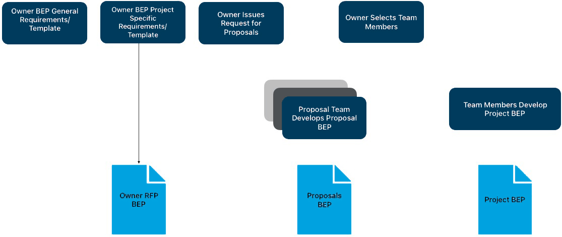
Figure 1.1: The Stages of BEP Development
Owner Request for Proposal BEP (RFP/BEP): As part of the owner's expanded role, this partial BEP is part of the Request for Proposal BEP used when considering teams for projects. ISO 19650-2 (2008) states that an owner should define their BIM requirements and standards before procuring (soliciting) a project team. The owner assembles information, data standards, and initial project requirements for the responding groups via an RFP BEP template. Proposers for a specific scope of work, e.g., a designer or constructor, respond to the owner’s RFP BEP with specific information identified in the Proposal BEP.
Proposal BEP: Each prospective party responding to an RFP will complete a proposal stage BEP, which includes information specific to meeting the scope of work, incorporating BIM recommendations, and appropriate responses. The proposing party must identify any exceptions or exclusions from the initial owner RFP BEP, if they exist. The owner will use this information to inform their selection or initiate further discussions regarding the effective use of BIM on the project.
Project BEP: Upon selecting the project team, the owner staff and the project team will collaborate to develop a Project BEP. This planning and documenting activity is comprehensive and outlines the execution strategy for BIM using a five-step procedure (shown below). Project BEP updates are made at various stages within the project as new team members or groups are integrated per the project phases.
An owner, proposer, or project team should follow a five-step procedure when developing a BEP. The procedure is designed to steer owners, proposers, and project team members through a structured process to create consistent plans for the appropriate stage. The five steps, shown in Figure 1.2, consist of identifying the appropriate BIM goals and uses on a project, designing the BIM execution process, defining the BIM deliverables, and identifying the supporting infrastructure to implement the plan successfully. These steps are introduced in this chapter, and a detailed description of each step is provided in Chapter 2. The guide references content from the BEP Template and Template BIM Process Maps.
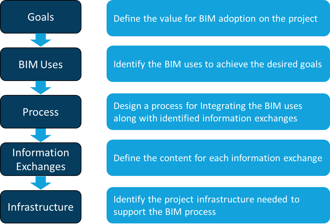
Figure 1.2: BEP Development Procedure
One of the most important steps in the planning process is to clearly define the potential value of BIM on the project and for project team members by defining the overall goals for BIM implementation. These goals could be based on project performance and include items such as reducing the schedule duration, achieving higher field productivity, increasing quality, reducing the cost of change orders, or obtaining important operational data for the facility. Goals may also relate to advancing the capabilities of the project team members; for example, the owner may wish to use the project as a pilot project to illustrate information exchanges between design, construction, and operations, or a design firm may seek to gain experience in the efficient use of digital design applications. Once the team has defined measurable goals, both from a project perspective and an organizational perspective, then the specific BIM uses on the project can be identified. An approach for the team to set goals is presented in Chapter Two of this guide.
Once the project team has defined measurable goals, both from a project perspective and an organizational perspective, then the specific BIM uses on the project should be identified. The U.S. National BIM Standard includes common uses for BIM, which have been identified through the initial BEP research along with industry expert review and definition . A BIM Use is a unique task or procedure on a project that can benefit from integrating BIM into that process. The eleven identified uses are not comprehensive but provide a good representation of the current uses of BIM within the industry. Several examples of BIM Uses include Capture Conditions, Author Design, Review Design, Layout Construction Work, etc. The team should identify and prioritize the appropriate BIM Uses they identified as beneficial to the project. The procedure for identifying BIM Use Cases for your project is discussed in Chapter Two.
Once the team has identified the BIM Use Cases, an overview process map defining the order and outcome of each use case should be developed (see Figure 1.3). This allows all team members to clearly understand how their work interacts with the tasks performed by others.
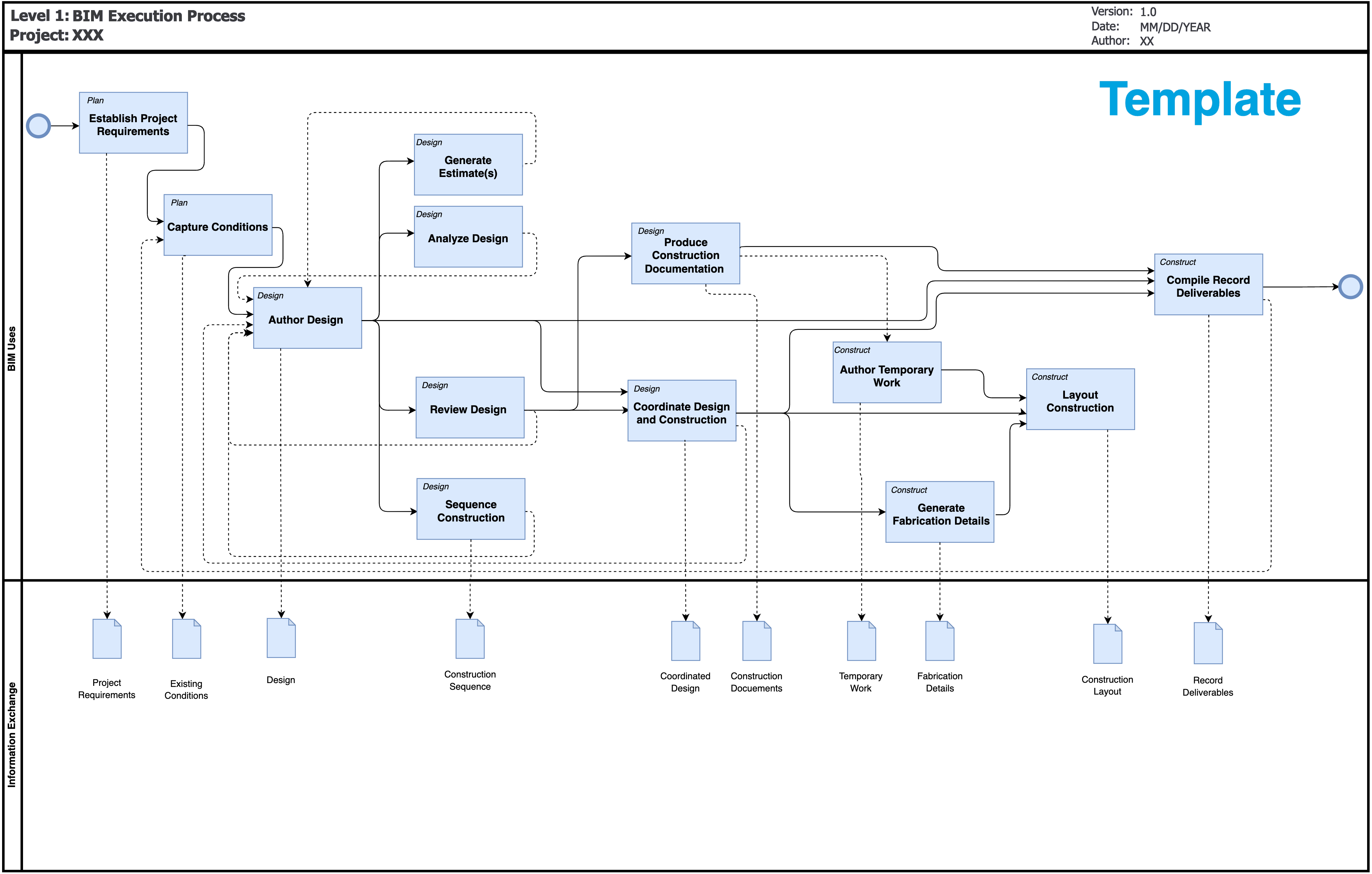
Figure 1.3: High-level BIM Execution Process
After the overview map is developed, more detailed process maps should be designed by each team member responsible for BIM Use Case. For example, the overview map will show how Capture Conditions, Author Design, Produce Construction Documents, Review Design, and Coordinate Design and Construction are sequenced and interrelated. A detailed map will show the detailed process that will be performed by an organization or, in some cases, several organizations, such may be the case for energy modeling. The procedure for designing the BIM execution process is discussed in Chapter Two.
Once the appropriate process maps have been developed, the information exchanges that occur between the project participants should be clearly identified. It is important for the team members, in particular, the author and receiver for each information exchange transaction, to clearly understand the information content. This information content for the exchange can be defined in the Information Exchange table, a portion of which is displayed as an example in Figure 1.4. The procedure for defining the information exchanges is discussed in Chapter Two.
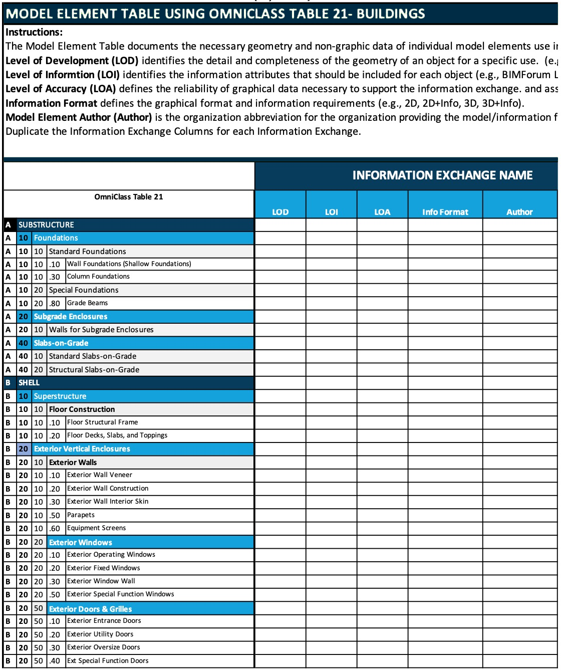
Figure 1.4: Model Element Table Sample
After the BIM uses for the project have been identified, the project process maps are customized, and the BIM deliverables are defined, the team must develop the infrastructure needed on the project to support the planned BIM process. This will include the definition of the delivery structure and contract language; defining communication procedures; defining the technology infrastructure; and identifying quality control procedures to ensure high-quality information models. The procedure for defining the infrastructure along with methods to implement and track progress is discussed in further detail in Chapter Two.
When complete, the BIM Plan should address the following categories of information:
Note: These items are discussed in further detail in Chapter Two of this guide.
The first step in developing a BIM Project Execution Plan is for the project team to identify the core reasons ‘why’ BIM can improve the overall delivery process and operations of the project.
The project team should outline project goals along with their potential relationship to BIM implementation. These project goals should be specific to the project at hand, measurable, and strive to improve success in the planning, design, construction, and operations of the facility. One category of goals may relate to general project performance, including reducing the project schedule duration, reducing the project cost, or increasing the overall quality of the project. Examples of quality goals include the development of a more energy-efficient design through the rapid iteration of energy modeling, creating higher quality installed designs through detailed 3D coordination of systems, or developing more accurate record models to improve the quality of performance modeling and commissioning.
Other goals may target the efficiency of specific tasks to allow for overall time or cost savings by the project participants. These goals include the use of modeling applications to create design documentation more efficiently, to develop estimates through automated takeoffs, or to reduce the time to enter data into the maintenance system. These items are only suggestions of potential goals that the project team may have when beginning to decide how to implement BIM on a project. It is by no means a comprehensive list, and it is essential to identify the specific goals that will provide an incentive for implementing BIM on the project.
A hypothetical new Laboratory Building constructed on a university campus will be used throughout the following three chapters to illustrate the steps in this guide. Sample project goals from this example project are shown in Table 2.1. Additionally, a blank Project Goals Worksheet is provided in Appendix A.
| Project Goals | ||||||
|---|---|---|---|---|---|---|
| Goal Description | Priority | Potential BIM Uses | Customer | Responsible Party | Constraints | Phase |
| Ensure a high quality of design and design | 1 | Author Design, Review Design | Designer | Construction Documents | ||
| Achieve the sustainability targets | 1 | Author Design, Review Design | Architect, MEP | Preliminary Design | ||
| Increase the productivity of field installation | 2 | Review Design, Coordinate Design and Construction, Layout Construction | Contractor | Construction | ||
| Accurately track the progress of construction | 2 | Visualize Construction Sequencing | Contractor | Construction | ||
| Develop an accurate record of the final building design for use in future renovation project | 2 | Coordinate Design and Construction, Compile Record Deliverables | Contractor, Designer, Facility | Commissioning | ||
| Effectively monitor the progress of design to ensure target for construction start is achieved | 3 | Review Design | Owner | Design Development | ||
| Accurately review the cost impact of changes in a timely manner | 3 | Author Design, Generate Estimate(s) | Contractor, Owner | Planning | ||
Table 2.1: Sample Project Goals
It is important to understand that some goals may relate to specific uses, while others may not. For example, if there is a project goal to increase field labor productivity and quality through large amounts of prefabrication, then the team can consider the ‘Coordinate Design and Construction’ Model Use which will allow the team to identify and correct potential geometric conflicts before construction. On the other hand, if the team’s goal was to increase the sustainability of the building project, several uses may assist in accomplishing that goal.
The goal of this chapter is to provide a method for identifying appropriate Model Uses given the project situation.
Sixteen BIM Uses, organized by project phase, have been identified and refined within the BIM Use Definition section of the U.S. National BIM Standard (reference Figure 2.2). It is important to note that there are many more potential uses for modeling on the project, so a team should not limit themselves to this list of uses. It is also important to note that very few teams would implement all of these BIM uses, but they are uses that are being implemented on projects.
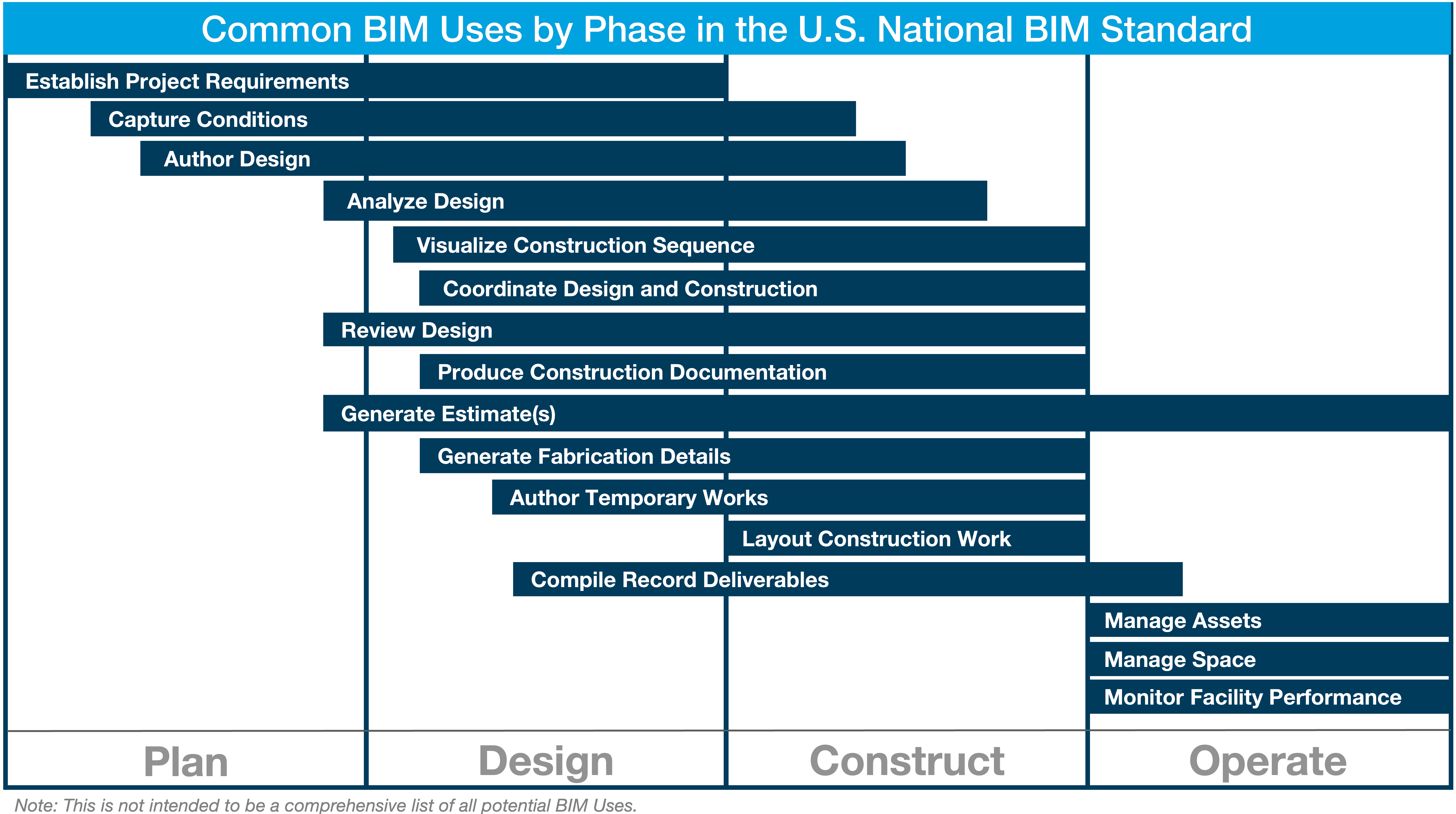
Figure 2.2: Common BIM Uses by Project Phase
A brief summary-level description of each of these BIM Uses is included in the BIM Use Definition (BUD) Standard. These descriptions were developed to provide a brief overview for project team members who may not be familiar with the BIM Uses and to provide additional information that the project team may find valuable during the selection process. Each description includes an overview of the BIM Use, potential benefits, required team competencies, and selected resources that can be referenced for additional information about the BIM Use. An example of a BIM Use description is shown in Figure 2.3.
Figure 2.3: High-level BIM Execution Process
For BIM to be implemented successfully, it is critical that team members understand the future use(s) of the information that they are developing. For example, when an architect adds a wall to the architectural model, that wall may carry information regarding the material quantities, mechanical properties, structural properties, and other data attributes. The architect needs to know if this information will be used in the future, and if so, how it will be used. The future use of this data can frequently impact the methods used to develop the model or identify quality control procedures related to the data accuracy for tasks relying on the information.
To emphasize the life cycle of the information, a core concept of the planning procedure is to identify the appropriate uses of modeling by beginning with the potential end-uses of the information in the model. To do so, the project team should first consider the later phases of a project to understand what information will be valuable to have during that phase. Then, they can move back through all of the project phases in reverse order (Operate, Construct, Design, and then Plan) as shown in Figure 2.4. This perspective to ‘begin with the end in mind’ will identify the downstream desired uses of information which should be supported by earlier processes in the lifecycle of the project. By identifying these downstream BIM Uses first, the team can focus on identifying reusable project information and important information exchanges.
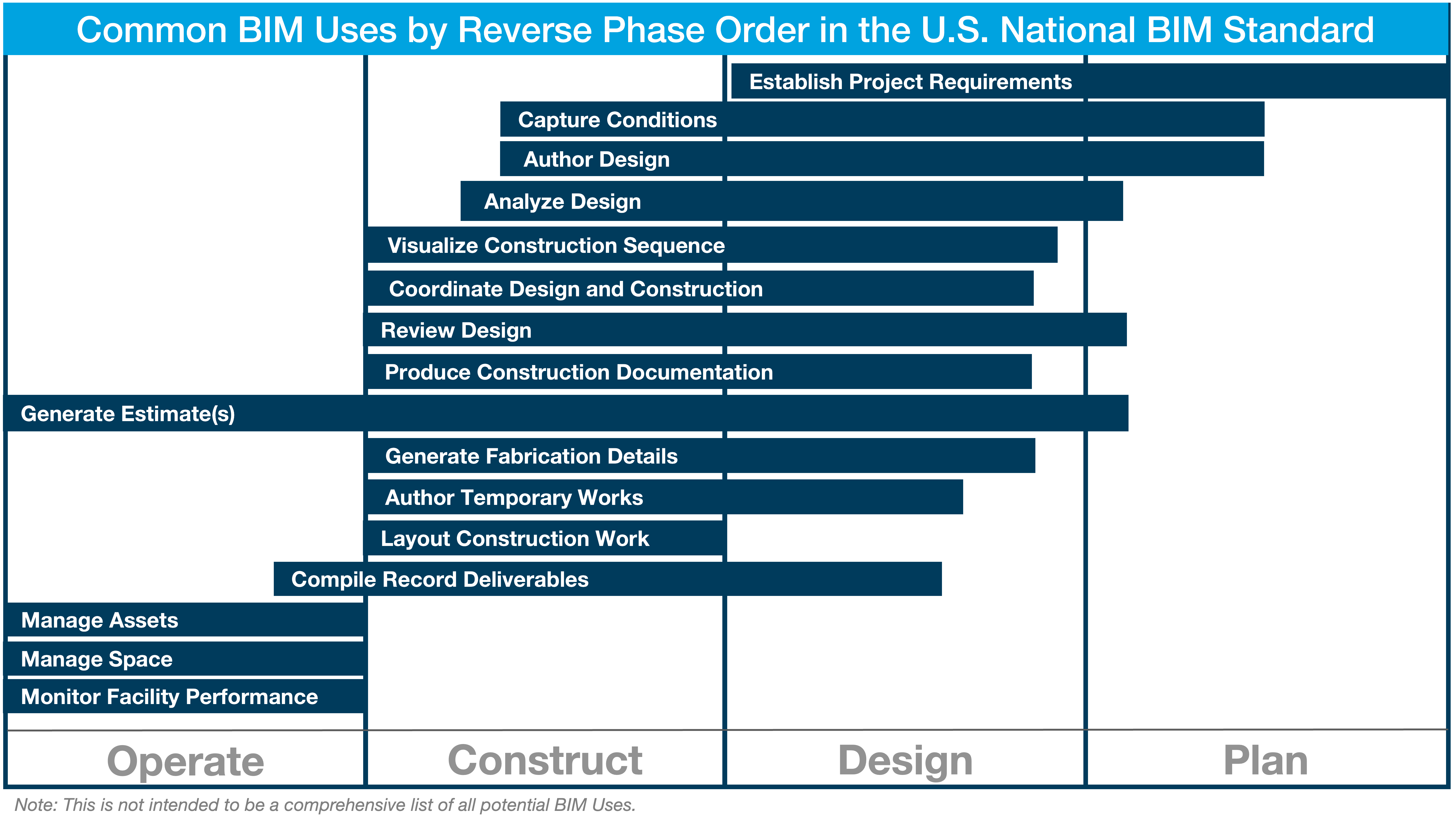
Figure 2.4: Common BIM Uses by Project Reverse Phase Order
Once the goals are defined, the project team should identify the appropriate tasks that the team would like to perform using BIM. This analysis of BIM Uses should initially focus on the desired outcomes for the overall process. Therefore, the team should begin with the operation phase, and identify the value for each of the BIM Uses as it specifically relates to the project by providing a High, Medium, or Low priority to each use. The team can then progress to each preceding project phase (construct, design, and plan).
To help facilitate this BIM Use review process, a BIM Use Selection Worksheet has been developed. This template includes a list of the potential BIM Uses, along with fields to review the value, responsible party, capabilities, additional notes, and the decision from the team on whether to implement the BIM Use. Please reference Figure 2.5 for an example of the BIM Use Selection Worksheet on an example project.

Figure 2.5: NBIMS-US™ Modules in Version 4
To complete the BIM Use Selection Worksheet, the team should proceed through the following steps with key project stakeholders.
1. Identify the potential BIM Uses
Definitions and explanations for each BIM Use are available by project phase in Appendix B. It is important that the team consider each of the potential uses and consider their relationship with the project goals.
2. Identify the responsible parties for each potential BIM Use
For each BIM Use that is being considered, at least one responsible party should be identified. The responsible parties include any team members who will be involved in the use if it is performed, along with potential outside participants that may be needed to assist with the implementation. List the lead responsible party first in the spreadsheet.
3. Rate the capabilities of each party for each BIM Use identified in the following categories
a. Resources – Does the organization have the resources necessary to implement the Model Use required? Some of the general resources required include:
b. Competency – Does the responsible party have the know-how to successfully implement the specific Model Use? To determine competency, the project team should understand the details of the Model Use and how it will be carried out on the specific project.
c. Experience – Has the responsible party performed the Model Use in the past? The team experience associated with each Model Use is vital to the success of the implementation.
4. Identify additional value and risk associated with each BIM Use
The team should consider the potential value gained, as well as, additional project risk that may be incurred by proceeding with each BIM Use. These value and risk elements should be incorporated into the ‘notes’ column of the BIM Use Selection Worksheet.
5. Determine whether or not to implement each BIM Use
The team should discuss each BIM Use in detail to determine whether or not the BIM Use is appropriate for the project given its characteristics (both project and team). This will require that the team determine the potential added value or benefit to the project and then compare this potential benefit to the cost of implementation. The team will also need to consider the risk elements associated with implementing or not implementing each particular BIM Use. For example, some BIM Uses can significantly reduce overall project risk, however, they may shift risk from one party to another. In other situations, the implementation of a BIM Use may potentially add risk for a party when they successfully perform their scope of work. Once all factors are considered, the team needs to make a ‘go / no go’ decision related to each BIM Use. Also understand that as the team decides to perform several BIM Uses, others may become easier to implement because the team members can leverage existing information. For example, if the architectural design is authored in a 3D parametric modeling application, then it is less expensive to implement Review Design.
After identifying each BIM Use, it is necessary to understand the implementation process for each BIM Use and the implementation process of the project as a whole. This chapter describes a procedure to design the BIM Project Execution Process. The process map developed in this step allows the team to understand the overall BIM process, identify the information exchanges that will be shared between multiple parties, and clearly define the various processes to be performed for the identified BIM Uses. The use of process mapping techniques allows the team to effectively perform this step. Process maps also serve as the basis for determining other important implementation topics including contract structure, model deliverable requirements, information technology infrastructure, and selection criteria for future team members.
Mapping the BIM Process for the project requires the project team to first develop an overview map that shows how the different Model Uses will be performed. Then, detailed BIM Use Process Maps are developed to define the specific BIM implementation at an increased level of detail. To implement this two-level approach, Business Process Modeling Notation (BPMN) has been adopted so that consistently formatted process maps will be created by the various project team members.
The Overview Map shows the relationship of BIM Uses on the project. This process map also contains the high-level information exchanges that occur throughout the project lifecycle. The details on how to create BIM Overall Map can be found in Appendix B.
Detailed BIM Use Process Maps are created for each identified BIM Use on the project to clearly define the sequence of various processes to be performed. These maps also identify the responsible parties for each process, reference information content, and the information exchanges which will be created and shared with other processes.
A BEP should identify important information exchanges and document the contents of each exchange. To define an exchange, the delivery team must understand what information is necessary to deliver each BIM Use. There are different approaches to defining an information exchange. One approach is to use a standard exchange definition. An example could be to define the exchange as an information delivery specification (IDS), which contains a clear definition of each element and attribute needed in the exchange. BuildingSMART International has some clearly defined exchange (see BuildingSMART International website).
A more common approach in the U.S. is to define the model elements in a Model Element Table (MET). The MET should be completed in the early stages of a project after designing and mapping the BIM process. A blank graphical version of the IE Worksheet is available in Appendix A and a Microsoft Excel version is available in the NBIMS BEP Resources as Template – Model Element Table – MS Excel Format. The following defines the general process of defining information exchange content. The detailed procedure for completing the MET is described in Appendix C.
Every element of a project does not need to be included for a model to be valuable. Therefore, it is important to only define the model components that are necessary to implement each BIM Use. Figure 2.6 depicts an example of how information flows through a BIM implementation process.
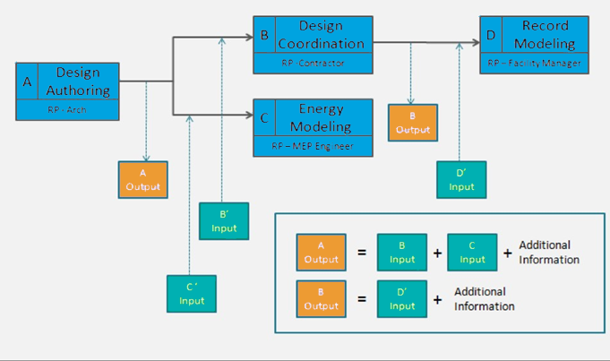
Figure 2.6: Information Flow Example
This figure was derived from the Level One process map described in Appendix B. Note that downstream BIM Uses are directly affected by what is produced by the upstream Use. Looking at this example from the perspective of a pull-driven approach, if the model information required to implement a particular BIM Use is not authored by an upstream team member, then the information needed must be created by the responsible party of that Use. Therefore, it is up to the project team to decide who should be authoring this information and when this information needs to be placed into the BIM. For simplicity purposes, it is only necessary that the team define one information exchange requirement for each BIM Use; although, there may be several exchanges that take place. These exchanges should be clarified in the Level Two process maps depicted in Appendix B.
After process map development, information exchanges between project participants should be clearly identified. It is important for the team members and, in particular, the author and receiver of each information exchange transaction to clearly understand the information content. One procedure for creating the information exchange requirements is based on Model Element Table developed by the BEP workgroup, detailed in Appendix A. It is important to note that there are several other standards or requirements that you can use to develop the information exchange definitions depending upon the project requirements, contracts, or preferences of the team. The team can use BIMForum or the Model Element Table we listed. One option is to perform a similar process as described in Appendix C, you can also use the BIMForum Level of Development spreadsheet to define each of the exchanges or the US Army Corps of Engineers Minimum Modeling Matrix (M3). While these tools vary in format and detail from the procedure in Appendix C, they can all be used to define the level of development for each model exchanged within the process.
The final step in the four-part BIM Project Execution Planning Procedure is to identify and define the project infrastructure required to effectively implement BIM as planned. Fourteen specific categories support the BIM project execution process, as displayed in Figure 2.7. These categories were developed after revising the last version of BEP, reviewing current execution plans, discussing the issues with industry experts, and revising through extensive review by various industry organizations.
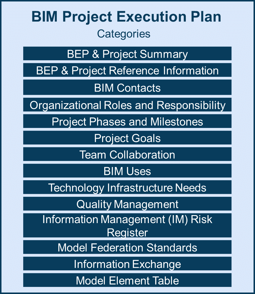
Figure 2.7: BEP Categories
Details information on each category of the BIM Project Execution Plan is discussed in Appendix D. Information for each category can vary significantly by project, therefore the goal of the description is to initiate discussion and address content areas and decisions that need to be made by the project team. Additionally, a template BIM Project Execution Plan has been developed and is available on the module website and referenced in BEP Best Practices. Please note that the information contained in the template will have to be customized based on the project. Additional information may be necessary, while other information could be removed.
This guide outlines a structured, five-step BIM Project Execution Planning Procedure, along with appropriate implementation guidelines. The implementation of this procedure has been performed on seven projects and within three organizations. By analyzing the successes and challenges encountered within these implementation case studies, the following ten recommendations for successful implementation were identified.
1) BIM Champion: Each project team needs a BIM Champion. A project using the BIM Project Execution Planning Procedure is more likely to succeed when there is at least one person with a strong desire to develop the BIM Plan. These champions take time to learn the procedure and work to help compile the final BIM Plan. They also market the value and necessity of the process to the other project team members. It is important that the champion(s) on a project encourages the team to take the time to plan the work, even if there is strong schedule pressure to begin developing model content before the completion of the planning process. The BIM champion(s) could be from any primary organization, but it is particularly important to have a champion within the owner organization. It is critical that the champion(s) have the authority to ensure the engagement of other project participants.
2) Owner Involvement: Owner involvement is critical throughout the entire process. By providing the guidelines for model and information deliverables, the owner can emphasize the importance of BIM implementation for reaching their desired end goals for the facility. Owner involvement and enthusiasm regarding the process can encourage project team members to seek the best processes that will benefit the entire project. Owners should consider writing a BIM Project Execution Plan into their contract documents to ensure that the planning process is performed to a level of detail that meets their expectations.
3) Culture of Collaboration: It is essential that the project team fosters an open environment of sharing and collaboration. The BIM Project Execution Planning Procedure requires organizations to provide information regarding their standard practices, including information exchange requirements. While certain contract structures can lead to collaboration challenges, the goal of this procedure is to have the team develop a BIM process containing deliverables that will benefit all members involved. To achieve this goal, the project team should have open lines of communication. The team members must buy in to the process and be willing to share their intellectual content with other team members.
4) Value of Integrative Delivery: The BIM Project Execution Planning Procedure can be adapted to different contracting structures. The BIM process can be more comprehensively adopted in more integrated project delivery approaches. However, none of the case studies used to validate the procedure were used with a specific Integrated Project Delivery (IPD) contract. The core steps of the procedure are helpful no matter which delivery method is used, but there are added challenges when implementing the planning when all core team members are not involved in the early stages of the project. Depending on the contract strategy, additional steps may be needed to ensure project planning success, and early assumptions may be needed to plan for future team members.
5) Plan Early: There is great value in early planning. If planning does not take place early, extra time may be needed to resolve inconsistencies downstream. This often results in more time and resources used than the original planning would have needed.
6) Living Document: The BIM Plan should be treated as a living document. When beginning the BIM Project Execution Planning Procedure, it is valuable to understand that the BEP must be flexible, and the plan should be reviewed and updated periodically. It is unrealistic to assume that the project team will have all information necessary to avoid assumptions that may need to be made to develop the BIM Plan at the project's inception. It will take time to populate the information because additional and new information must be incorporated as project team members are added. A clear change management process should be followed for these revisions. Project team members should follow any contract requirements if they feel that any revisions may be considered a change in scope.
7) Periodic Review: Once an initial plan is developed, it must be reviewed regularly. A revision schedule should be set based on a frequency the project team considers appropriate. Throughout the project's life, it is important to keep the initial project goals in mind to ensure that the team works towards their completion. If there is any deviation, the team should reassessment or rededicate themselves to the goals.
8) Resource the Planning Process: The appropriate resources must be made available to ensure planning success. It is important to keep in mind that the level of effort needed for this process should not be underestimated. Project teams must consider the time allocated for planning when generating both the project schedule and project budget. Due to the learning curve associated with this process, teams should overestimate the time it will take to produce a BIM Project Execution Plan. The time associated with the learning curve can be reduced by educating involved team members before delving into the process. Without proper planning before the project specific meetings begin, many unexpected issues may arise that could have been solved at an earlier time.
9) The Value of an Organizational Plan: Developing an organizational BIM Project Execution Plan before project inception can decrease project planning time. By performing organizational level planning, the team can reduce the amount of time spent on each step of the planning process for all team members and maintain a manageable planning scope by defining their standard goals, uses, processes, and information exchanges. You may wish to reference the BIM Planning Guide for Facility Owners, available in NBIMS-US Version 3, for additional information related to BIM planning at an organizational level.
10) Customizing the BEP Template: The BIM Project Execution Planning Procedure can be adapted for multiple uses and situations beyond the original scope of the project. Even if project teams take only what they need from the procedure and do not complete the entire process, these projects can still create detailed BIM Plans. Teams have the ability to revise the template documents to fit their specific processes, without modifying any of the core steps of the planning procedure. These teams then have the ability to eventually add other portions of the procedure, which will further assist with their planning.
The BIM Project Execution Planning Procedure has helped project teams develop detailed plans for their projects. These plans outline the goals, process, information exchanges, and infrastructure for BIM implementation. By developing and following these plans, the teams can make a significant impact on the degree of successful BIM implementation. The procedure does take time and resources, particularly the first time an organization is involved in this level of planning, but the benefits of developing the detailed plan far outweigh the resources expended.
This appendix includes images from the BEP template along with the two template Model Element Table template files. These files are available as downloadable spreadsheets in the Resources section.

Figure A-1: BIM Execution Plan Template Introduction

Figure A-2: BEP Cover Page Template
| BEP & PROJECT SUMMARY |
|---|
| Instructions: Include a BEP Executive Summary explaining the process of how this document will be developed. It is a strategic summary of how the team wi11 maximize BIM technology and information to meet the project goals and responsibilities of a project. Include a Project Summary of the project. |
| BEP EXECUTIVE SUMMARY |
| BEP PROJECT DESCRIPTION |
Figure A-3: BEP & Project Summary Template
| BEP & PROJECT REFERENCE INFORMATION | |
|---|---|
| Instructions: Provide project, contact, and BEP information that will be used in this BEP. | |
| Project Reference Information | |
| Project Name | |
| Project Owner Name | |
| Project Legal Address | |
| Sold | |
| Project Legal Address | City: | State: | Zip: |
| Facility Type Classification | |
| Facility Type Name | |
| Project Delivery Method | |
| Project Information Req. Title | |
| Owner Modeling Guide Title | |
| Owner Modeling Guide Location | |
| BEP Development Standard | |
| BEP Path | |
| BEP Data Format | |
| Acknowledgements | |
| Team Selection Procedure | |
| BIM Contracting Procedure | |
| BEP Version Log | |||||||
|---|---|---|---|---|---|---|---|
| Version Number | Date | Description | Creator Org. |
Creator Contact |
Approval Org. |
Approval Contact |
Approval Status |
Add rows as needed.
| Project Identification Table | |
|---|---|
| Project Identification Description | Project Identification Value |
Add rows as needed.
| Project Certifications Information | |
|---|---|
| Certification Information | Certification Value |
Add rows as needed.
| Project Metrics Value | ||
|---|---|---|
| Project Metric Name | Project Metric Value | Project Metric Unit |
Add rows as needed.
Figure A-4: BEP & Project Reference Information Template
| BIM CONTACTS | ||||
|---|---|---|---|---|
| Instructions: Organizations and persons with roles and responsibilities for project BIM activities should be documented in the BEP. Additional rows may be added as needed. | ||||
| Project Organizations | ||||
| Organization Name | Abbr. | Phone Number | Office Location | Org. Role |
Add rows as needed.
| Contacts | |||||
|---|---|---|---|---|---|
| Org. Abbr. | Name | Contact Role | Email Address | Phone Number | Primary Location |
Add rows as needed.
Figure A-5: BIM Contacts Template
| ORGANIZATIONAL ROLES & RESPONSIBILITIES | ||||
|---|---|---|---|---|
| Instructions: Provide a clear description of the various BIM related roles on a project along with their responsibilities. Identify if they are required by contract, and provide a brief abbreviated code for use in the contracts table. | ||||
| BIM Roles & Responsibilities | ||||
| Contact Role | Role Description | Role Responsibility | Req. Contract | Role Code |
Add rows as needed.
Figure A-6: Organizational Roles & Responsibilities Template
| PROJECT PHASES & MILESTONES | |||||
|---|---|---|---|---|---|
| Instructions: Define the various phases of the project, e.g., planning, design, construction, along with discrete milestones. A phase should have a start and finish date, while a milestone is on a specific date and resides within a phase. | |||||
| Project Phases | |||||
| Phase Name | Phase Description | Est. Start Date |
Est. Completion Date |
Actual Start Date |
Actual Completion Date |
Add rows as needed.
| Project Milestones | ||||
|---|---|---|---|---|
| Milestone Name | Milestone Description | Est. Date | Actual Date | Phase |
Add rows as needed.
Figure A-7: Project Phases and Milestones Template
| PROJECT GOALS | ||||||
|---|---|---|---|---|---|---|
| Instructions: Identify project goals that would add value to the project and how it can relate to BIM Uses. These should be documented as part of the BEP process. Once collected, the goals and BIM Uses are prioritized and the final list of requirements is documented in the BEP. | ||||||
| Project Goals | ||||||
| Goal Description | Priority | Potential BIM Uses | Customer | Responsible Party | Constraints | Phase |
Add rows as needed.
Figure A-8: Project Goals Template
| PROJECT PHASES & MILESTONES | |||||
|---|---|---|---|---|---|
| Instructions: Teams must act collaboratively. Document the collaboration activities to be performed, including meetings, modeling coordination, and information-sharing schedules. | |||||
| Collaboration Strategy Description | |||||
| Collaboration Activities | |||||
| Activity Type | Responsible Party | Phase | Frequency | Participants | Location |
Add rows as needed.
Figure A-9: Team Collaboration Template
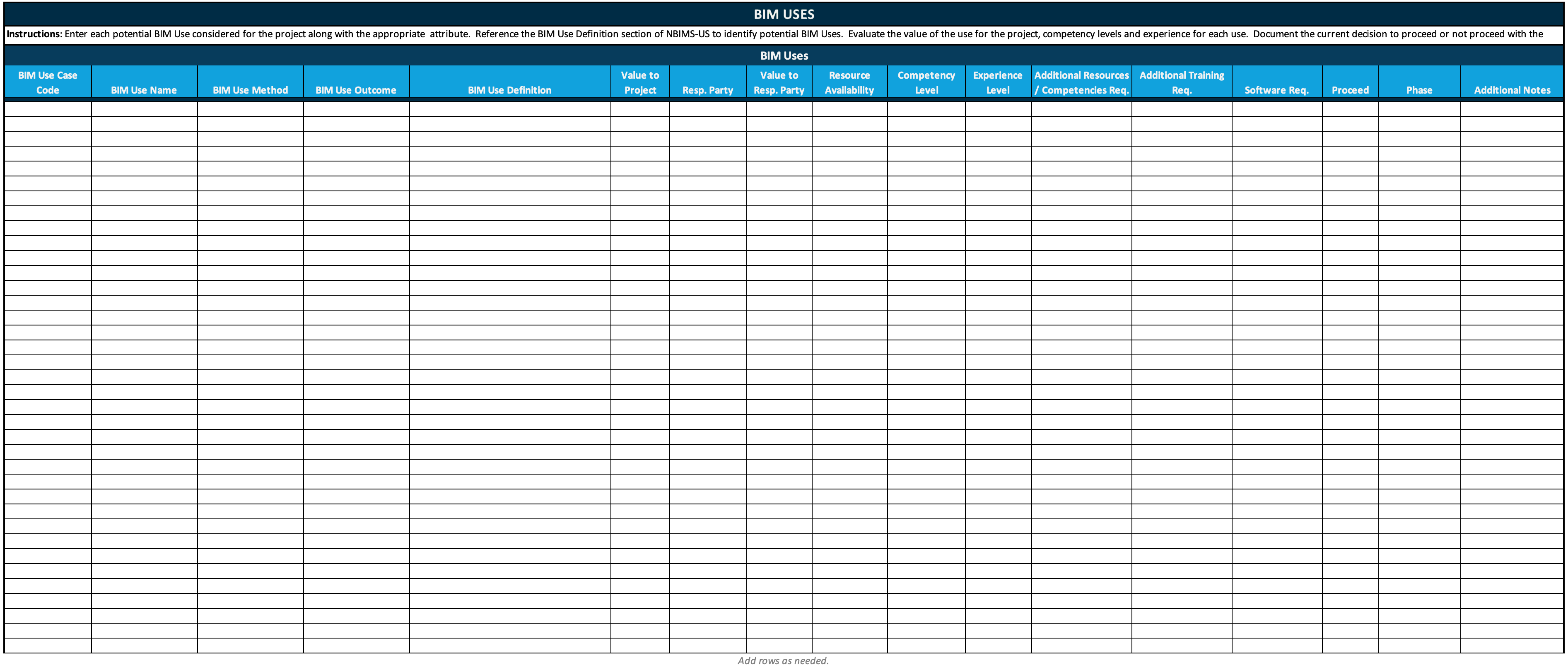
Figure A-10: BIM Uses Template
| BIM USE PROCESS | |
|---|---|
| Instructions: Include a path to the Level 1 BIM Use process map showing the interacation of all BIM Uses. Include a list of the Level 2 BIM Uses and links to the Level 2 process maps for each BIM Use. | |
| Level 1 BIM Use Process Map Path | |
| Level 2 BIM Use Case Process Maps | |
| BIM Use Name | BIM Use Process Map Path |
Add rows as needed.
Figure A-11: BIM Use Process Template
| TECHNOLOGICAL INFRASTRUCTURE NEEDS | ||||||||||
|---|---|---|---|---|---|---|---|---|---|---|
| Instructions: Provide required software and hardware to be used on the project. Include how it can relate to BIM Uses. The software documentation includes what software, versions, who uses the tool, how it is used in the BIM or project process, and additional information to manage the software during the project lifecycle. Include a table of the types of hardware that will be used for Building Information Management. | ||||||||||
| Software Table | ||||||||||
| Software Name | Version | File Format | Max Model Size | BIM Use | Resp. Party | Discipline | Contact | Hardware Considerations | Software Update Process | Notes |
Add rows as needed.
| Hardware Table | ||||||
|---|---|---|---|---|---|---|
| Hardware Name | Owner | Specification | Quantity | BIM Use | Procurement Approach |
Notes |
Add rows as needed.
Figure A-12: Technological Infrastructure Needs (1) Template
| TECHNOLOGICAL INFRASTRUCTURE NEEDS | |||
|---|---|---|---|
| Instructions: Provide the methods of access to internet on the project. Include how and where the models can be accessed. | |||
| Internet Access | |||
| Location Description | Access Method | Speed | Security Requirements |
Add rows as needed.
| Shared Model Development Resources | ||||
|---|---|---|---|---|
| Resouce Name | Version | Owner | Description | BIM Use |
Add rows as needed.
| Information Sharing Platforms | |||||
|---|---|---|---|---|---|
| Platform Name | Version | Owner | Manager | Capability Breadth | Compliance w. CDE Req. |
Add rows as needed.
Figure A-13: Technological Infrastructure Needs (2) Template
| QUALITY MANAGEMENT | |||||||
|---|---|---|---|---|---|---|---|
| Instructions: Provide a description of the overall strategy that will be used to manage quality of the model and derivative information. Include quality control activities that will be used on the project. Required tasks are defined in the BEP tables. Additional information should be documented in the QM strategy. | |||||||
| Quality Management Strategy | |||||||
| Quality Control Activity | |||||||
| Activity Type | Contract Req. | Description | Resp. Party | Software | Frequency | Location | Reference Doc. |
Add rows as needed.
Figure A-14: Quality Management (1) Template
| QUALITY MANAGEMENT | |||
|---|---|---|---|
| Instructions: Provide information regarding the model data accuracy and how the software will be tested for compatibility. | |||
| Model Data Accuracy | |||
| Discipline | Existing Conditions Data Source |
Survey Data Type | Level of Accuracy |
Add rows as needed.
| Software Compatibility Testing | |||
|---|---|---|---|
| Export Software Application |
Import Software Application |
Test Date | Notes |
Add rows as needed.
Figure A-15: Quality Management (2) Template
| IM RISK REGISTER | |||||||
|---|---|---|---|---|---|---|---|
| Instructions: Add all risk items associated with information management tasks. These risk register entries should also be placed within the overall project risk register. | |||||||
| Risk Register | |||||||
| Risk Title | Description | Probablity | Consequence | Mitigation Methods | Category | Status | Resp. Party |
Add rows as needed.
Figure A-16: IM Risk Register Template
| MODEL FEDERATION STANDARDS | ||||
|---|---|---|---|---|
| Instructions: Multiple models (by discipline and use) are shared and integrated during the project. Provide the strategy and methods used for sharing models and data. | ||||
| Model Federation Description | ||||
| Naming Conventions | ||||
| Convention Type | Naming Convention Title Req. | Naming Convention Version | Description | Location of Naming Conv. Details |
Add rows as needed.
| Reference Coordinate System | |
| UTM Zone | |
| Horizontal Units of Measurement | |
| Vertical Units of Measurement | |
| Horizontal Datum | |
| Vertical Datum | |
| Project Origin Longitude | |
| Project Origin Latitude | |
| Project Origin Elevation | |
| Project Grid Offset from True N | |
| Reference Grid | |
| Reference Survey |
| Building Information Management Standards | ||
|---|---|---|
| Standard Name | Standard Version | Standard Purpose |
Add rows as needed.
Figure A-17: Model Federation Standards Template
Figure A-18: Information Exchange Template
Figure A-19: Model Element Table Template Using OnmiClass Table 21-Buildings
The following is a portion of the table. The full table can be found in the Resources tab.
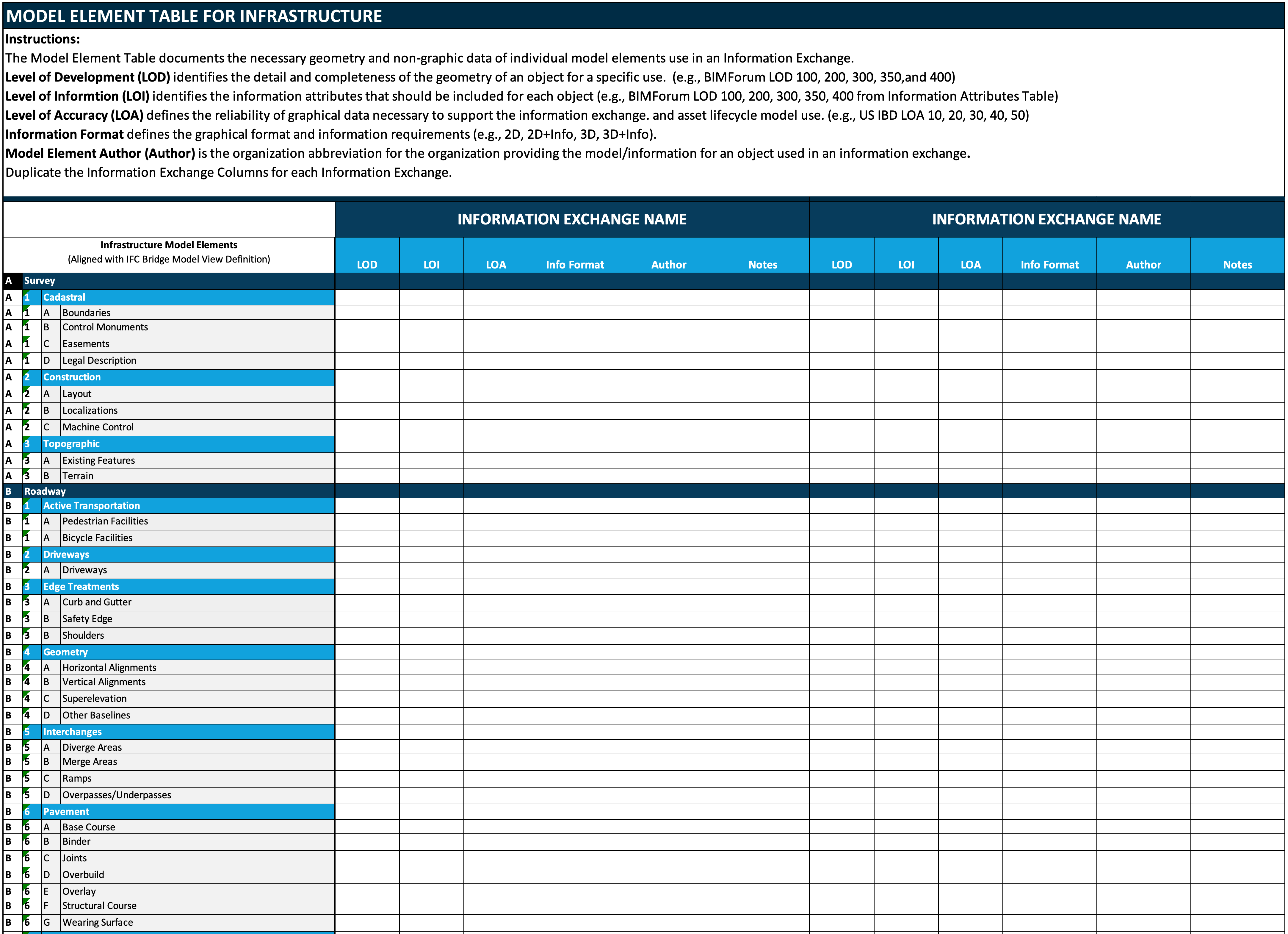
Figure A-20: Model Element Table Template - Infrastructure
The following is a portion of the table. The full table can be found in Resources tab.
This section details how to create a BIM Overview Map.
Once the team identifies the BIM Uses for the project (refer to the BIM Use Selection section in Chapter 2), the team can start the mapping process by adding each of the BIM Uses as a process within the map. It is important to understand that a BIM Use may be added to the overview map at several locations if it is performed several times within the project life cycle.
To help achieve this task, a template diagrams.net file containing process maps is provided in the Resources section of this module. A diagrams.net template objects file is also posted in the same location and can be used by the project team to develop the process maps easily. If the project team members do not have Microsoft Visio, the team can use other process mapping or graphics software to create the process maps. Additionally, versions of the templates are in Appendix D – Template Process Maps.
After developing the process for each implemented BIM Use on the project, the team should sequentially order these processes. One of the purposes of the Overview Map is to identify the phase for each BIM Use (e.g., plan, design, construct, or operate) and provide the team with the implementation sequence. For simplistic purposes, the BIM Uses should align with the BIM deliverables schedule.
Responsible Parties should be clearly identified for each process. For some processes, this may be an easy task, but for others, it may not. It is important in all cases to consider which team member is best suited to successfully complete the task. Additionally, some processes may have multiple responsible parties. The identified party will be responsible for clearly defining the information required to implement the process as well as the information produced by the process.
The graphical notation and information format for the processes within the BIM Overview Map are included in Figure B.1. Each process should include a process name, project phase, and the responsible party. Each process should also include a ‘Detailed Map’ title which points to the detailed map (Level Two map) for the process. This detailed map notation is used since several processes may share the same detailed map. For example, a construction management company may perform cost estimating from the building information provided by the designer. The Construction Manager may perform this estimate during the schematic design, design development, and construction document phase, but it may use the same detailed workflow to accomplish this task, which can represent a single detailed map. Therefore, the process for performing the three estimates should be added to the high-level map at three locations, but the team can reference a single detailed map for further information.
The BIM Overview Map includes the critical information exchanges which are either internal to a particular process or shared between processes and responsible parties. In general, it is vital to include all information exchanges that will pass from one party to another. In current applications, these exchanges are typically implemented through the transfer of a data file, although it could also include the entry of information into a common database. All the information exchanges identified in the BIM Overview Map should be detailed, as defined in the following detailed BIM Use Map.
The exchanges which originate from a process box are exchanges that are internal to a process. The exchanges that originate or flow into the sequence line are external exchanges that are shared between high-level processes. For example, Figure B.1 shows information exchanges arising from the ‘Author Design’ process box for the Laboratory Project. These exchanges, although internal to the 3D Coordination Process, should be identified in the BIM Overview Map since multiple parties author the exchanged information. This ensures that the exchanges will be detailed using the information exchange definition procedure described in the following detailed BIM Use Map.
Figure B.1:
To illustrate the results of an overview mapping task, the BIM Overview Map for the Laboratory Project defines the overall BIM Uses that the team has employed for the project which is Capture Conditions, Author Design, Visualize Construction Sequence, Author Temporary Work, Generate Fabrication Details, Coordinate Design and Construction, Compile Record Deliverables (reference Figure B.2). It also identifies the BIM Use Phase, for example, Author Design is performed during the design development phase, whereas Coordinate Design and Construction and Compile Record Deliverables are performed during the Construction Phase. The map also identifies the critical Information Exchanges that are shared between different parties.
Figure B.2:
After creating an Overview Map, a Detailed BIM Use Process Map must be created for each identified BIM Use to clearly define the sequence of the various processes performed within that BIM Use. It is important to realize that each project and company is unique, so there may be many potential methods that a team could use to achieve a particular process. Therefore, these template process maps need to be customized by project teams to accomplish the project and organizational goals. For example, the template process map may need to be tailored to integrate a specific computer application workflow or project teamwork sequence.
A Detailed BIM Use Process Map includes three categories of information which are represented on the left side of the process map and the elements are included in the horizontal lines (referred to as ‘lanes’ in the BPMN mapping notation):
The core processes of BIM Use need to be identified. These are represented by a ‘rectangular box’ symbol within BPMN. These are placed in sequential order within the Process swim lane.
Next, dependencies between the processes are defined. This is accomplished by defining the connections between processes. The project team needs to identify the predecessor and successor of each process. In some cases, it may be possible to have multiple successors and /or predecessors. These processes are then connected using the ‘sequence flow’ lines in BPMN.
a. Reference Information: Identify the informational resources needed to accomplish the BIM Use in the ‘Reference Information’ lane. Examples of reference information include cost databases, weather data, and product data.
b. Information Exchanges: All the exchanges (internal and external) should be defined in the ‘Information Exchange’ lane. These exchanges are further detailed in Appendix C.
c. Responsible Party: Identifies the responsible party for each process. Figure B.3 displays how to represent this information in the process map.
Figure B.3:
A gateway can be used to ensure that the deliverables or results of a process are met. It could also modify the process path based on a decision. Gateways provide the opportunity for the project team to represent any decisions, iterations or quality control checks required before the completion of a BIM task. Figure B.4 demonstrates how this can be accomplished within a Detailed BIM Process Map (Level-Two Map).
This Detailed Process Map can be further used for other projects by the project team. It should be saved and reviewed at various times throughout the BIM Implementation process. Throughout the project, detailed process maps should be updated periodically to reflect the actual workflows implemented on the project. Additionally, after project completion, it may be helpful to review the process maps to compare the actual process used versus the planned process. Detailed process maps can likely be used on future projects. Please reference Figure B.5 for an example of a Detailed BIM Use Process Map.
For BIM Execution, the preferred notation for process mapping development is the Business Process Modeling Notation (BPMN) developed by the Management Group. One of the key elements of the BPMN is the visual appearance of the process map in terms of the symbols and markers used. These should conform to the shapes defined in the BPMN specification.
The following symbols can be used to develop a Process Map for the BIM Plan: Table B.6: Process Mapping Notation for BIM Process Maps.
The following is the procedure to define information exchange requirements for each BIM Use:
Information Exchanges that are shared between two parties should be defined. One BIM Use may have multiple exchanges; however, to simplify the process, only one exchange is necessary to document each Use. Also, the time of exchange should be derived from the Level One Map. This ensures that the involved parties know when the BIM deliverables are expected to be completed along with the project’s schedule. The project phases should also be identified in the project-specific contract language in the Infrastructure section of BEP. When possible, the BIM Use exchanges should be listed in chronological order to give a visual representation of the progression of the model requirement.
After the project team has established the Information Exchanges (IE), the team should select an element breakdown structure for the project. Currently, the Model Element Table uses the CSI Uniformat II structure; however, other options are available on the BIM Execution project website, for example, the BIMForum Level of Development spreadsheet or the US Army Corps of Engineers Minimum Modeling Matrix (M3)
To define each information exchange, the following information should be documented:
1. Information Exchange (IE) Name: the name of information exchange (do we have any principle). It is recommended to develop the exchange name from the BIM Use title unless there is a specific exchange name already defined, e.g., for IFC Model View Definitions. An example would be to remove the initial verb from the BIM Use Title and append the word 'Model'. For example, 'Author Design' would become a 'Design Model', and if there are multiple model deliverables from a BIM Use, additional detail should be added to the title.
2. IE Description: the description of information exchange to describe the purpose of the IE.
3. Milestone: Define the project Milestone for the information exchange.
4. Sender – Identify all project team members that will send the information to perform a future BIM Use.
5. Receiver – Identify all project team members receiving the information to perform a future BIM Use.
6. Frequency: the frequency of the IE. Some information exchanges may only occur once, but others may be transmitted multiple times, e.g., 3D coordination models. If the exchange occurs multiple times, define the typical cycle or frequency, i.e., weekly or monthly.
7. Due Date: The date the exchange is due if there is a specific date.
9. Location (URL): The URL of the IE, which will be linked with ....
10. Software: List the specific software application(s), as well as, the version that will be used to manipulate the model during each BIM Use by the receiver. This is pertinent to identify any interoperability that may exist between exchanges.
11. Source Format: List the file format of the source information.
12. IE Format: Define the expected file format (or form?? online vs onsite) of IE.
13. BIM Use: Record the connect BIM Use for IE.
14. Req. Contract: Document whether the specific exchange is required by the sender in their contract (value should be yes or no).
15. Permitted Uses: The exchange should define the future permitted uses that can rely upon the information, e.g., analyze energy or analyze structure, from an architectural model.
16. Req. Approvals: Identify all project team members who should review and approve the IE.
17. Req. IE Delivery: Identify the requirement for IE delivery.
18. IE Definition (?)
<<ADD IMAGE OF BEP TEMPLATE - INFORMATION EXCHANGE TABLE>>
Each line item in an Information Exchange should have a party who is responsible for authoring the information. The responsibility for creating the information should lie with the party that can produce it with the highest level of efficiency. Additionally, the time of input should be when it is needed by the model receiver, based on the level 1 process map. The worksheet can be sorted according to the responsible party to determine one's scope for each BIM deliverable. Table C.2 below is a list of potentially responsible parties.
Once the information requirements are defined, it is necessary for the project team to discuss the specific element, Level of Development (LOD), Level of Information (LOI), Level of Accuracy (LOA), File Format, and Model Element Author. LOD identifies the detail and completeness of the geometry/non-geometry of an object for a specific use. (Pull-down menu 100, 200, 300, 350, 400, and 500). LOI defines the information attributes that should be included for each object. LOA defines the reliability of non-graphic data necessary to support the information exchange. and asset lifecycle model use. (Pull-down menu - 10, 20, 30, 40, 50). File format defines the graphic format and information requirement (e.g., 2D, 2D+information, 3D, 3D+information). The Author is the person or organization providing the model/information for an object used in information exchange.
Senders and receivers of IE should work together to define the model element table. Receivers clarify information requirements and senders describe the information that they can provide. If the send information and receive information do not match, two potential remedial actions could be taken:
The development of the BIM Plan is a collaborative process. Some portions of the procedure, e.g., discussing the overall project goals, are collaborative tasks, while other portions, e.g., defining the required file structure or detailed information exchange, do not necessarily require collaboration. The key to successfully developing the plan is to ensure that meetings are scheduled for the collaborative tasks when needed, and that the noncollaborative tasks are completed in a timely manner, in preparation for these meetings. The BIM Plan can be developed through a series of collaborative meetings, followed by work tasks which take place between the meetings. A series of four meetings have been defined to develop the BIM Plan. The goal of presenting the four-meeting series is to illustrate one structure that the team can use to effectively develop the plan. For some projects, the team may be able to reduce the number of meetings through effective collaboration between meetings.
The four meetings proposed to develop the BIM Project Execution Plan are closely aligned with the primary steps outlined in Chapter One. The meetings and interim tasks include:
The first meeting should focus on the discussion of the overall goals for implementing BIM, along with identifying the BIM Uses. A draft agenda for this meeting would include:
This meeting should be attended by senior management personnel and BIM management staff for all involved participants including the owner, designers, contractors, and key subcontractors.
After the initial kick-off meeting, the organizations should clearly understand who will be responsible for the defined tasks, and in what sequences the BIM Uses will be executed. The responsible party for the Level One map should clearly document and distribute it to the project team for review prior to the following meeting. Each responsible party for the specified BIM Uses should also draft their workflow prior to the Design BIM Project Execution Process meeting (Meeting 2).
The Project Specific BIM Use Process Maps shall contain a detailed process plan that clearly defines the different activities to be performed, who will perform them, and what information will be created and shared with future processes. The agenda for this meeting will include:
This meeting should be attended by the owner, BIM managers, and project manager for the project. It may also be valuable to have contracting managers in attendance or have them briefed soon after this meeting.
After the Design BIM Project Execution Process meeting, the team must focus on developing the information exchanges. Each responsible party for an exchange should take the lead in developing the information exchanges. The authors of the information exchange will need to coordinate with the information receivers to ensure that they have developed consistent information exchanges with minimal inconsistencies to discuss at Meeting Three. The team members should also prepare for the discussions regarding infrastructure requirements which will occur in Meeting Three. Team members should compile examples of typical methods that they have used or wish to use on the project to share with the team.
Implementation
The agenda for this meeting will include:
This meeting should be attended by the BIM managers. It may also be valuable to have contracting managers in attendance or briefed soon after this meeting.
The categories and information should be compiled into the final BIM Execution Plan format and distributed to the project team in preparation for the final plan review meeting. Meeting 4: Review Final BIM Project Execution Plan The agenda for this meeting will include:
This meeting should be attended by the owner, BIM managers, and all parties that are responsible for the identified BIM Uses.
Once the meetings are complete, the BIM Project Execution Plan should be distributed to all parties and approved as appropriate for the project and contracting structure. Team members should ensure that the plan monitoring and updating procedure is implemented into the project controls system.
One of the first tasks of the team is to determine the planning meeting schedule. This schedule should identify the defined meetings, along with the scheduled dates for the meeting. The team may decide that they wish to spread the planning procedure across several weeks with one of the defined meetings each week or every other week. But they also may wish to define an accelerated planning schedule over several days with the team specifically focused on the development of the plan.
Once the initial BIM Execution Plan is created, it will need to be continuously communicated, monitored and updated throughout the project. In particular, the Project Execution Plan should be embedded into appropriate contracts, and then updated as needed when new team members join the project team. At a minimum, it is valuable for the BIM managers from the various team members to meet on a monthly basis to discuss the progress of the information modeling initiatives on the project and to address any implementation challenges that team members may be encountering. These meetings may be incorporated with other team meetings, but it is important to specifically address issues that may arise in the implementation of the plan. It is important for the team to continuously modify the planned process as needed due to the addition of team members, revisions to available technology, changes to the overall project conditions, and to reflect the actual process that evolved. The team should agree to a formal plan for accepting updates to the plan, and then accurately document any changes to the original plan for communication to other team members, as well as for accurate future use and reference.
This Change Log documents that revisions that were made, originally to the BIM Project Execution Planning Guide, through Version 3. Following Version 3, the guideline was retitled to the BIM Execution Planning Guidelines and the changes are focused on transitioning from a stand-alone guideline into this online module guideline.
Version 4.0 has been developed to integrate the BEP Guide directly within the U.S. National BIM Standard. This included a number of significant revisions to the structure, content, and formatting of the BEP Guide, including the following:
| Title | Description | |
|---|---|---|
| NBIMS-US BEP Template (Excel) | The BEP Template is an Excel spreadsheet that is used to create project specific BEPs. | Download |
| NBIMS-US BEP Template (PDF) | This is the PDF version of the NBIMS-US BEP Template | Download |
| NBIMS-US BEP Standard Tables | The NBIMS BEP Standard Tables is a compilation of the tables from the BEP Standard in excel format. They are provided for ease of use and adoption among project teams. | Download |
| NBIMS-US BEP Model Element Template (MET) - Buildings | The Model Element Table documents the necessary geometry and non-graphic data of individual model elements use in an Information Exchange for buildings. | Download |
| NBIMS-US BEP Model Element Template (MET) - Infrastructure | The Model Element Table documents the necessary geometry and non-graphic data of individual model elements use in an Information Exchange for infrastructure. | Download |
| RFP BEP JSON Schema | A JSON data schema file containing all required BEP elements for the Owner RFP BEP and all other optional elements. | Download |
| Proposal BEP JSON Schema | A JSON data schema file containing all required Proposal BEP elements for the proposal BEP and all optional elements. | Download |
| Project BEP JSON Schema | A JSON data schema file containing all required Project BEP elements for the project BEP and all optional elements. | Download |
Innovative Solutions for the Built Environment
Established by the United States Congress, NIBS' mission is to serve the public interest by advancing building science and technology to improve the built environment.
Subscribe to receive NIBS news and information.

